
Motor stator

A motor stator and positioning convex technology, applied in the direction of magnetic circuit shape/style/structure, connection with control/drive circuit, magnetic circuit static parts, etc., can solve the problem of affecting motor performance and service life, poor electrical connection of pins , starting torque and other problems, to avoid loosening or poor electrical connection, improve performance and service life

Pending Publication Date: 2020-04-03
SUNON ELECTRONICS (BEIHAI) CO LTD
View PDF1 Cites 1 Cited by
  • Summary
  • Abstract
  • Description
  • Claims
  • Application Information

AI Technical Summary

Problems solved by technology

[0003] However, although the stator of the above-mentioned existing motor can be electrically connected to the circuit board through the pins, when the motor is started, due to the large starting torque, the pins are likely to be unstable, resulting in loosening of the stator. In severe cases, it will cause the problem of poor electrical connection of the pin, which will affect the performance and service life of the motor

Method used


Image

  • Motor stator
  • Motor stator
  • Motor stator

Examples


Embodiment Construction

[0046] In order to make the above-mentioned and other objects, features and advantages of the present invention more obvious and understandable, the preferred embodiments of the present invention are listed below, together with the accompanying drawings, and are described in detail as follows:

[0047] In the present invention, the directionality described below or its approximate terms, such as "front", "rear", "left", "right", "up (top)", "down (bottom)", "inside", "outside" , "side", etc., mainly refer to the directions of the drawings, and each direction or its approximate terms are only used to assist in explaining and understanding the various embodiments of the present invention, and are not intended to limit the present invention.

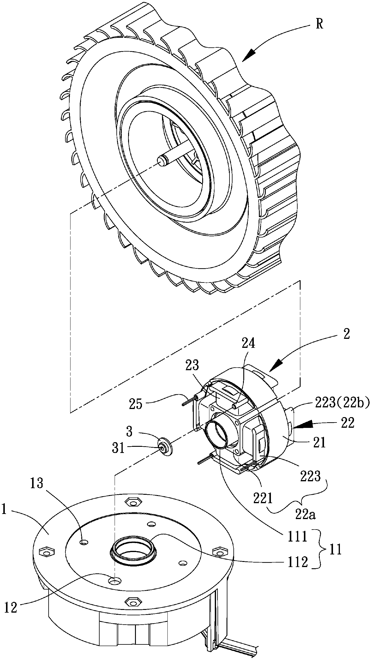
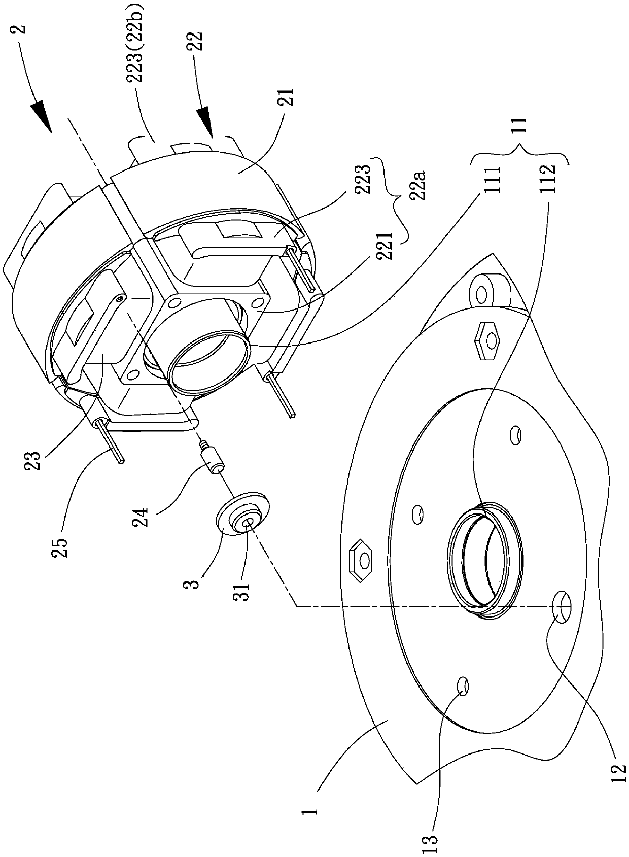
[0048] Please refer to figure 1 As shown, it is the first embodiment of the motor stator of the present invention, which includes a base 1, a winding group 2 and at least one elastic bundle set 3, the winding set 2 and the elastic bundle se...


PUM


Abstract

The invention provides a motor stator and the objective of the invention is to solve the problem that a stator is easy to loosen when an existing motor is started. The motor stator comprises a base provided with at least one positioning hole located in the periphery of a coupling part; and a winding group which is provided with a magnetic pole piece combined with an insulating piece, wherein a coil is wound on the insulating piece, at least one positioning convex column is connected with the insulating piece, the positioning convex columns are arranged in the positioning holes in a penetratingmanner, and the positioning convex columns are not electrically connected with the coil; and an elastic binding sleeve piece which is sleeved in the positioning convex columns and is propped againstthe inner walls of the positioning holes.

Description

technical field [0001] The invention relates to a motor stator, in particular to a motor stator capable of preventing the stator from loosening. Background technique [0002] Existing motors have a stator coupled to a base, the stator has an iron core wound with a coil, a pin of the stator is coupled to a circuit board through a hole in the base, and the pin is electrically connected to a circuit board. A rotor rotatably couples the stator with the coil and the circuit board. In this way, the coil can drive the rotor to rotate relative to the stator after the coil is energized, and an embodiment similar to the conventional motor has been disclosed in the patent case of Chinese Publication No. 1409888 "External Rotor Brushless DC Motor". [0003] However, although the stator of the above-mentioned existing motor can be electrically connected to the circuit board through the pins, when the motor is started, due to the large starting torque, the pins are likely to be unstable,...

Claims


Application Information

Patent Timeline
Patent Type & Authority Applications(China)
IPC IPC(8): H02K1/14H02K11/30
CPCH02K1/14H02K11/30
Inventor 洪银树林建良
Owner SUNON ELECTRONICS (BEIHAI) CO LTD
Learn More