
Synchronous belt pulley driving structure, robot drive base and tabletop-level mechanical arm

A technology of synchronous pulley and driving structure, applied in the field of driving, can solve the problems of high cost, difficult loading and unloading, poor stability, etc., and achieve the effect of improving service life, ensuring control accuracy and reducing material cost

Pending Publication Date: 2020-04-03
SHENZHEN YUEJIANG TECH CO LTD
View PDF0 Cites 29 Cited by
  • Summary
  • Abstract
  • Description
  • Claims
  • Application Information

AI Technical Summary

Problems solved by technology

[0002] Some desktop-level or lightweight robots or mechanical arms often use DC motors with reducers as drive devices, and some desktop-level or lightweight robots use DC motors with synchronous pulleys as drive devices. Unsatisfactory. On the one hand, there are usually complex structures under the condition of ensuring the driving accuracy, which requires a high degree of integration, resulting in poor stability, high cost, and difficult loading and unloading. On the other hand In general, if you want to simplify the structure, you usually sacrifice the control accuracy, so there is an urgent need for a driving structure with low cost, simple structure, relatively low structural integration, and good control accuracy.

Method used


Image

  • Synchronous belt pulley driving structure, robot drive base and tabletop-level mechanical arm
  • Synchronous belt pulley driving structure, robot drive base and tabletop-level mechanical arm
  • Synchronous belt pulley driving structure, robot drive base and tabletop-level mechanical arm

Examples


Embodiment Construction

[0029] The following will clearly and completely describe the technical solutions in the embodiments of the present invention with reference to the accompanying drawings in the embodiments of the present invention. Obviously, the described embodiments are some of the embodiments of the present invention, but not all of them. Based on the embodiments of the present invention, all other embodiments obtained by persons of ordinary skill in the art without creative efforts fall within the protection scope of the present invention.

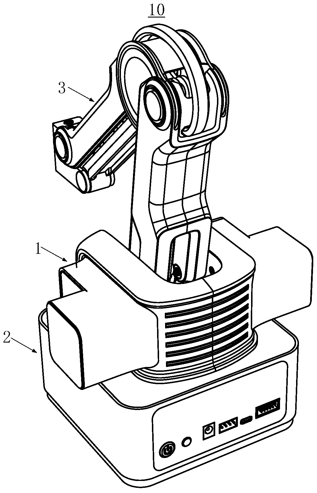
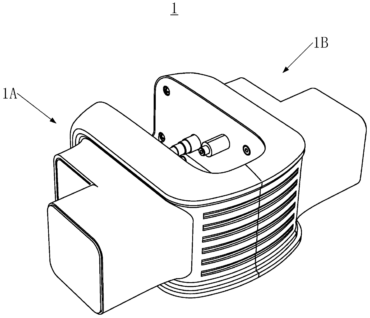
[0030] Please also refer to Figure 1-2 , figure 1 is a schematic structural diagram of a desktop-level robotic arm in an embodiment of the present invention, figure 2 yes figure 1 Schematic diagram of the structure of the driving base of the desktop-level robotic arm in the embodiment.

[0031] In some embodiments, the desktop-level mechanical arm 10 includes a driving base 1, a base 2 and a mechanical arm body 3, the driving base 1 is connected t...


PUM


Abstract

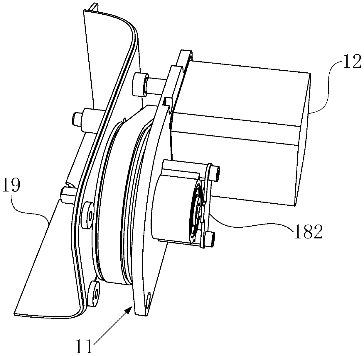
The invention provides a synchronous belt pulley driving structure, a robot drive base and a tabletop-level mechanical arm. By means of ingeniously arranging the space relationship of a stepping motor, a first synchronous belt pulley, a second synchronous belt pulley, a synchronous belt, an output shaft, an encoder code disk and an encoder reading head portion on a base plate, arranging the transmission structure of the stepping motor, the first synchronous belt pulley, the second synchronous belt pulley, the synchronous belt and the output shaft and adopting the structural arrangement of theencoder code disk and the encoder reading head portion which are used for reading the rotation quantity of the output shaft, the synchronous belt pulley driving structure has a relatively low integration level since the structure is simple and parts are not excessive, and since the rotation quantity of the output shaft can be read, the control precision is guaranteed; and in this way, the materialcost, the installation cost and the maintenance cost are lowered, and the service life of the driving structure is effectively prolonged.

Description

technical field [0001] The invention relates to the field of drive technology, in particular to a synchronous pulley drive structure, a robot drive base and a desktop-level mechanical arm. Background technique [0002] Some desktop-level or lightweight robots or mechanical arms often use DC motors with reducers as drive devices, and some desktop-level or lightweight robots use DC motors with synchronous pulleys as drive devices. Then, these solutions often use Unsatisfactory. On the one hand, there are usually complex structures in the case of ensuring driving accuracy, which requires a high degree of integration, resulting in poor stability, high cost, and difficult assembly and disassembly. On the other hand In general, if you want to simplify the structure, you usually sacrifice the control accuracy, so there is an urgent need for a driving structure with low cost, simple structure, relatively low structural integration, and good control accuracy. Contents of the invent...

Claims


Application Information

Patent Timeline
Patent Type & Authority Applications(China)
IPC IPC(8): B25J9/00B25J9/10B25J9/12B25J13/00
CPCB25J9/0009B25J9/104B25J9/126B25J13/00
Inventor 汪金星刘培超刘主福
Owner SHENZHEN YUEJIANG TECH CO LTD
Learn More