Switching device
A switch device and switch technology, which is applied in the direction of electric switches, electrical components, circuits, etc., can solve the problem that the switch device cannot be switched on and off, and achieve the effect of improving user experience and simple and reliable structure
- Summary
- Abstract
- Description
- Claims
- Application Information
AI Technical Summary
Problems solved by technology
Method used
Image

Examples
Embodiment 1
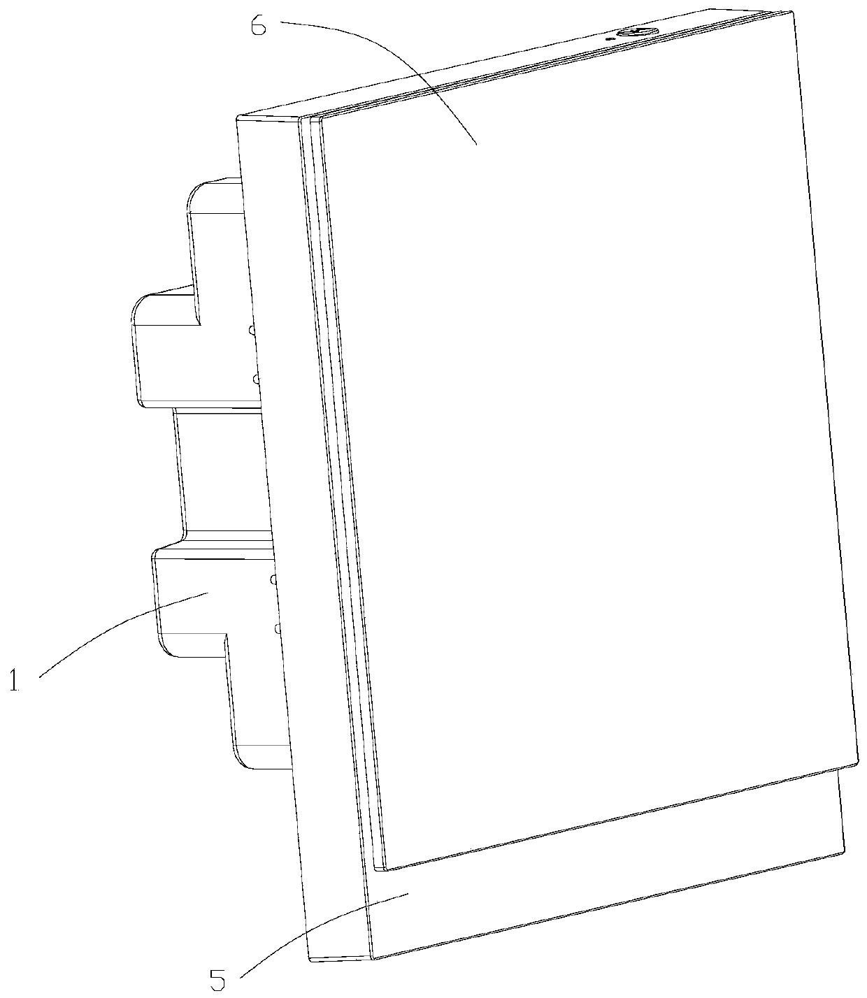
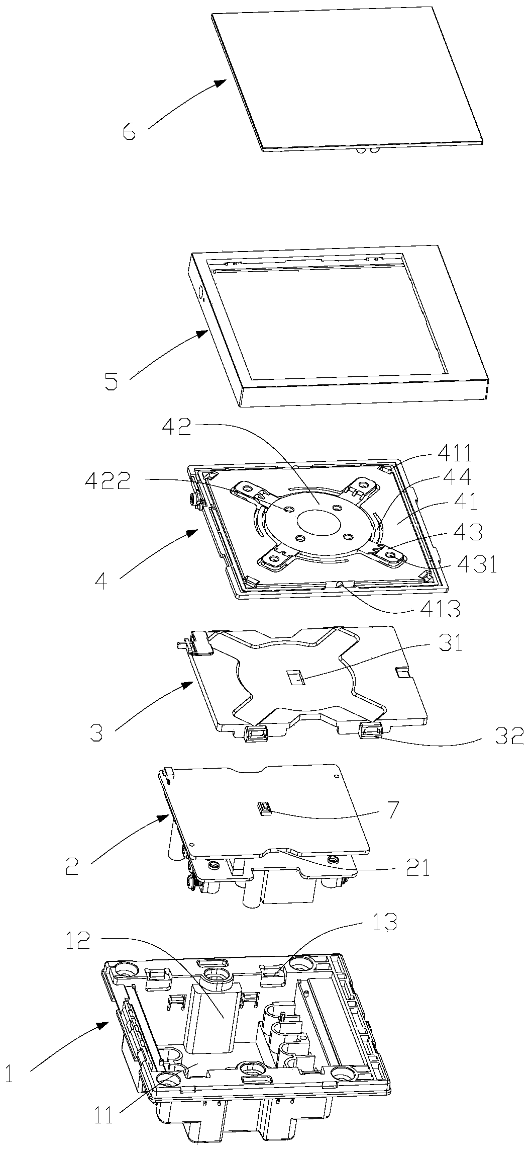
[0029] Such as Figure 1-Figure 5 As mentioned above, the embodiment of the present invention provides a switch device, including a fixing frame 1 , a circuit board assembly 2 , a pressing plate 3 , a bracket 4 , a panel 5 , a button 6 and a switch 7 .
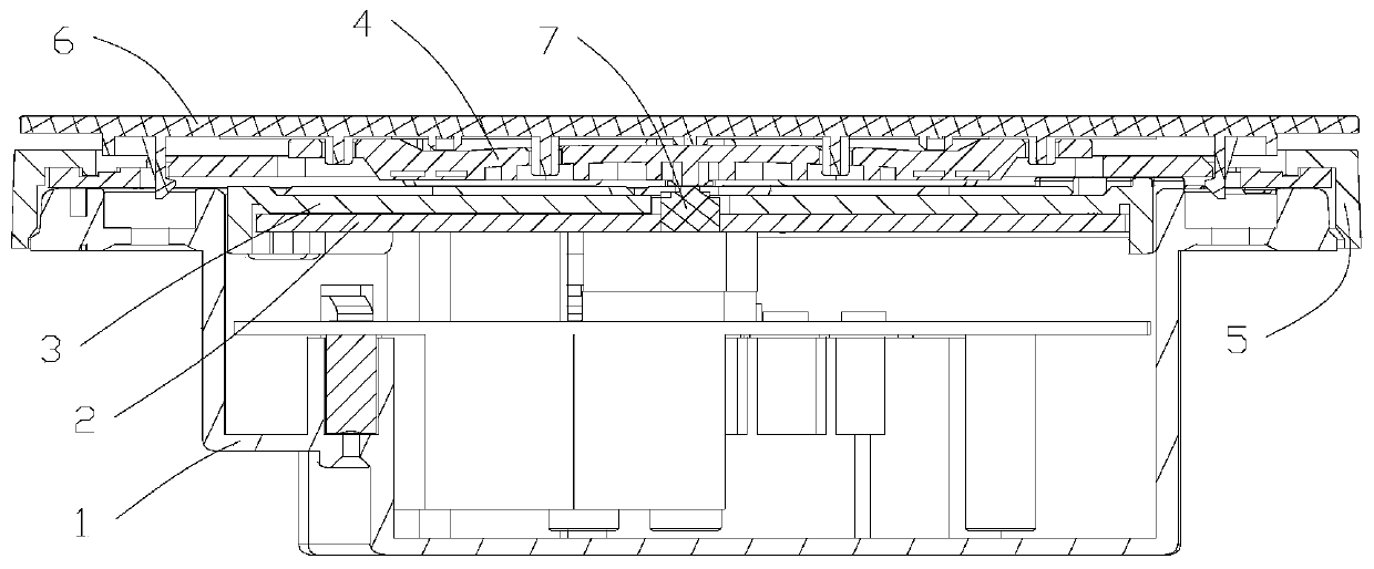
[0030] Wherein, the fixed frame 1 is provided with a cavity 11, the cavity 11 has an opening, the circuit board assembly 2 is arranged in the cavity 11, and the circuit board assembly 2 is fixed in the cavity 11 by the pressing plate 3, the switch 7 is installed on the circuit On the plate assembly 2, and the switch 7 is located at the opening of the cavity 11, since the switch 7 needs to be exposed for pressing, a via hole 31 for avoiding the opening is also provided in the middle of the pressing plate 3, and the switch 7 extends from the via hole 31. out. The panel 5 is installed at the opening of the cavity 11 of the fixed frame 1, and is used to cover the fixed frame 1, and can also limit the position of the bracket 4. Th...
Embodiment 2
[0045] Such as image 3 , Figure 5 As shown, in an optional embodiment of the present invention, a boss 421 is provided on the surface of the trigger portion 42 opposite to the switch 7 , and the boss 421 is adapted to the switch 7 .
[0046] The switch 7 is arranged in the middle of the circuit board assembly 2 , and similarly, the boss 421 is arranged in the middle of the trigger part 42 . The shapes and sizes of the two can be approximately the same, and it is also feasible that the surface area of the boss 421 is larger or smaller than the surface area of the switch 7 , which is not limited here.
[0047] After the user presses the button 6, the pressing part 43 and the trigger part 42 are driven to move down. As the trigger part 42 moves down, the boss 421 and the switch 7 interfere with each other, and the switch 7 is pressed to realize the conduction or disconnection of the circuit.
[0048] Due to the mutual cooperation between the boss 421 and the switch 7, it...
Embodiment 3
[0051] Such as Figure 2-Figure 5 As shown, in an optional embodiment of the present invention, the pressing portion 43 is Z-shaped, formed by integrally extending and bending the edge of the triggering portion 42 . The plane of the free end of the Z-shaped pressing portion 43 is higher than the plane of the triggering portion 42 , which can well support the button 6 . And the Z-shaped structure has good rigidity, and can support the button 6 for a long time when there is no external force, and can also be quickly reset after the external force, preventing the pressing part 43 from being unable to drive the trigger part due to fatigue failure caused by pressing deformation 42 moves.
[0052] Furthermore, reinforcing ribs are provided at the bends of the pressing portion 43 . The ribs can further improve the rigidity of the pressing portion 43 , preventing the pressing portion 43 from being unable to drive the triggering portion 42 to move due to fatigue failure caused by pre...
PUM
 Abstract
Description
Claims
Application Information
 - R&D
- Intellectual Property
- Life Sciences
- Materials
- Tech Scout
- Unparalleled Data Quality
- Higher Quality Content
- 60% Fewer Hallucinations
Browse by: Latest US Patents, China's latest patents, Technical Efficacy Thesaurus, Application Domain, Technology Topic, Popular Technical Reports.
© 2025 PatSnap. All rights reserved.Legal|Privacy policy|Modern Slavery Act Transparency Statement|Sitemap|About US| Contact US: help@patsnap.com