Anti-vibration quick-release lock

A technology of locking nails and lock seats, applied in mechanical equipment, connecting components, etc., can solve the problems of poor anti-vibration ability of quick-release locks and achieve high anti-vibration effect

Pending Publication Date: 2020-03-17
北京首航科学技术开发有限公司
View PDF0 Cites 2 Cited by
  • Summary
  • Abstract
  • Description
  • Claims
  • Application Information

AI Technical Summary

Problems solved by technology

[0004] The purpose of the present invention is to provide an anti-vibration quick-release lock, which is used to solve the problem of poor anti-vibration ability of the quick-release lock in the prior art

Method used


Image

  • Anti-vibration quick-release lock
  • Anti-vibration quick-release lock
  • Anti-vibration quick-release lock

Examples


Embodiment Construction

[0044]In order to make the object, technical solution and advantages of the present invention clearer, the present invention will be further described in detail below in conjunction with the accompanying drawings and embodiments. It should be understood that the specific embodiments described here are only used to explain the present invention, and are not intended to limit the present invention, that is, the described embodiments are only some of the embodiments of the present invention, but not all of the embodiments. The components of the embodiments of the invention generally described and illustrated in the figures herein may be arranged and designed in a variety of different configurations.

[0045] Accordingly, the following detailed description of the embodiments of the invention provided in the accompanying drawings is not intended to limit the scope of the claimed invention, but merely represents selected embodiments of the invention. Based on the embodiments of the ...


PUM


Abstract

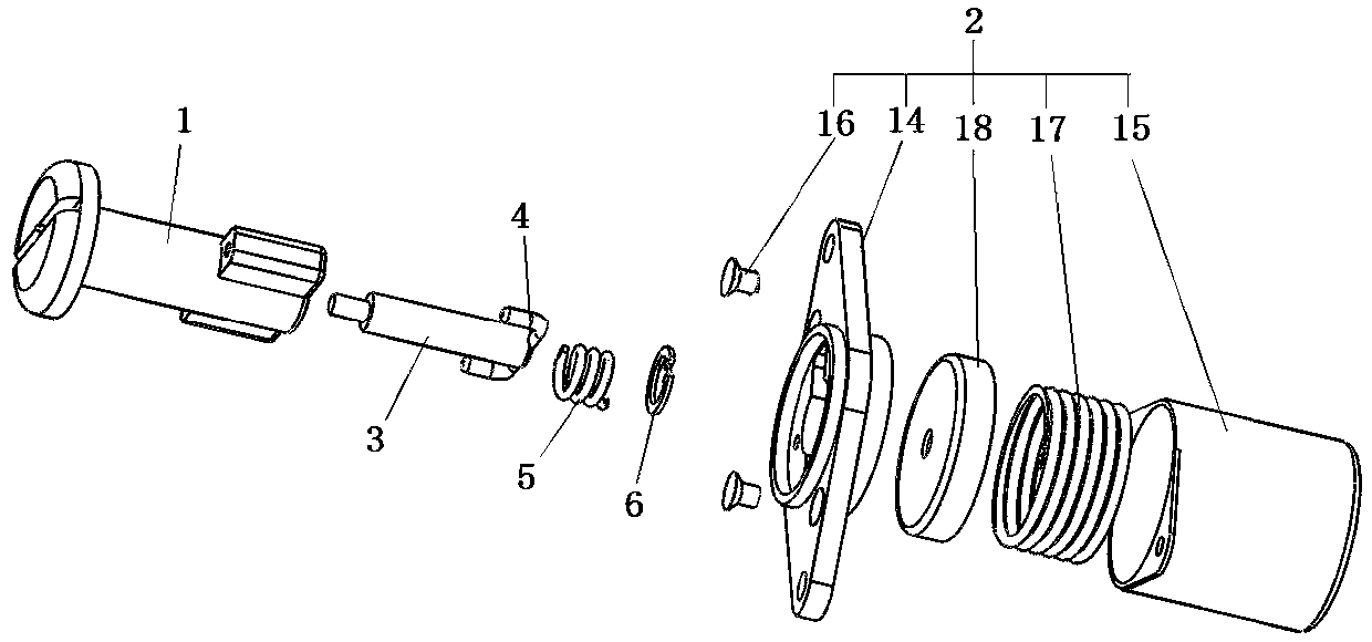
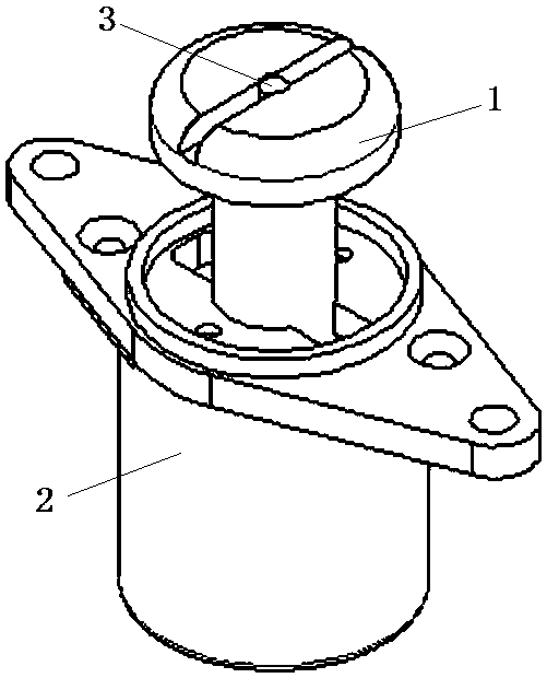
The invention relates to an anti-vibration quick-release lock. The quick-release lock comprises a lock pin, a lock seat, a push rod and a stop pin, wherein a lock pin head is arranged at one end of the lock pin, a locking head is arranged at the other end of the lock pin, the lock pin is provided with a mounting hole extending in the axial direction, and the mounting hole penetrates through the lock pin head; the lock seat is provided with a containing cavity allowing the locking head to extend in, a stop piece is arranged at the end, close to the lock pin head, of the containing cavity, and alocking head penetrating hole is formed in the stop piece; the push rod is movably assembled in the mounting hole of the lock pin; the stop pin and the push rod are relatively fixed, and the stop pinis provided with a stop part extending in the axial direction of the lock pin; a slide way allowing the stop pin to move is arranged in the locking head of the lock pin and extends to the side face,facing the lock pin head, of the locking head in the axial direction of the lock pin; a lock hole into which the stop part extends is formed in the stop piece of the lock seat; a lock pin spring is installed at the end, away from the lock pin head, of the lock pin and used for pushing the stop pin or the push rod; and the lock pin is provided with a stop structure for limiting the push rod from axially disengaging from the mounting hole. The quick-release lock is used for solving the problem that the existing quick-release lock is poor in vibration resistance.

Description

technical field [0001] The invention relates to an anti-vibration quick release lock. Background technique [0002] A lot of equipment is equipped with a cover, observation window and other structures that need to be opened and closed frequently, so as to check the operating status of the machine. In order to facilitate the opening and closing of structures such as flaps, the locking of structures such as flaps and their corresponding substrates is usually achieved through quick release locks. The quick release lock generally includes a locking nail and a lock seat. The end of the locking nail away from the locking nail head is provided with a locking head, and the lock seat is provided with a perforation for the locking head of the locking nail to pass through. The locking head has many shapes. It is in the shape of a cuboid, and the perforation is a rectangular hole adapted to the shape of the locking head. When the length direction of the locking head is parallel to the ...

Claims


Application Information

Patent Timeline
IPC IPC(8): F16B21/04
CPCF16B21/04
Inventor 张艳雷王志河方翠平汪新雷徐猛王亚利
Owner 北京首航科学技术开发有限公司
Why Eureka
Try Eureka