
LED display module, LED display screen and control equipment of LED display screen

An LED display and LED lamp module technology, applied in static indicators, instruments, etc., can solve the problems of high cost, the control system cannot automatically identify the display module information and working status, and the black screen power consumption is high.

Active Publication Date: 2020-03-13
SHENZHEN LAMP TECH
View PDF5 Cites 2 Cited by
  • Summary
  • Abstract
  • Description
  • Claims
  • Application Information

AI Technical Summary

Problems solved by technology

However, judging from the current use of most LED displays, they have not yet achieved real intelligence, and are still at a relatively primary application level. Some so-called smart LED displays on the market often only integrate some common functions. module only
[0004] At present, the data transmission of most LED displays is unidirectional. The control system controls the display module by transmitting data, but the display module has no feedback data. Realize many intelligent functions like the display terminal
On the other hand, the current solution of adding Flash memory to the display module or integrating the receiving card into the display module brings high cost, and the cost performance is too low
[0005] In addition, when the display module has no feedback data, the LED display will have many shortcomings: First, the control system often cannot automatically identify the information and working status of the display module, and professional and complex manual work is required to achieve playback and maintenance. Second, the power supply module of the display screen cannot realize intelligent power supply and power saving according to the information and status of the display module.

Method used


Image

  • LED display module, LED display screen and control equipment of LED display screen
  • LED display module, LED display screen and control equipment of LED display screen
  • LED display module, LED display screen and control equipment of LED display screen

Examples


Embodiment Construction

[0026] In order to make the technical problems, technical solutions and beneficial effects to be solved by the present invention clearer and clearer, the present invention will be further described in detail below in conjunction with the accompanying drawings and embodiments. It should be understood that the specific embodiments described here are only for explaining the present invention, and are not intended to limit the present invention.

[0027] In the following description, use of suffixes such as 'module', 'part' or 'unit' for denoting elements is only for facilitating description of the present invention and has no specific meaning by itself. Therefore, 'module', 'part' or 'unit' may be used in combination.

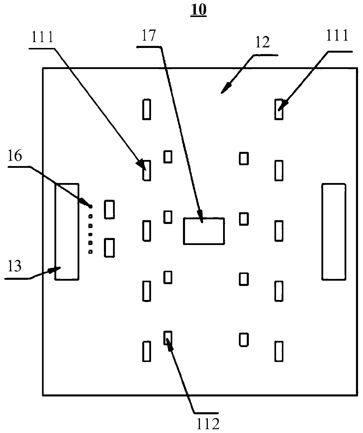
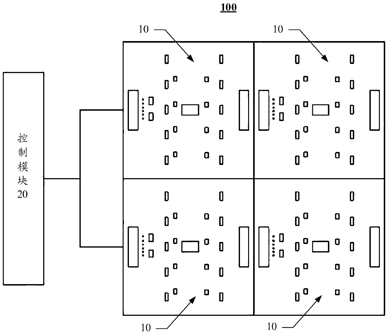
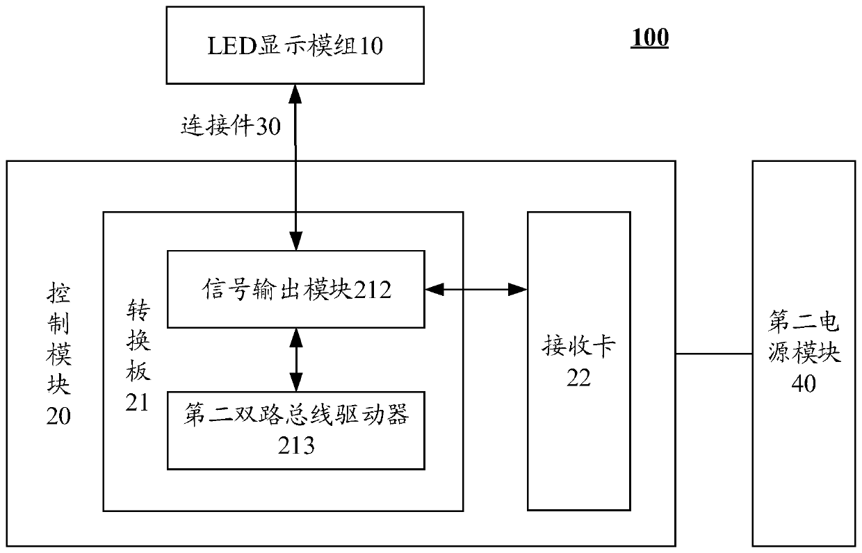
[0028] In one embodiment, such as figure 1 As shown, the present invention provides an LED display module, the LED display module 10 includes an LED lamp module 11, a PCB (Printed Circuit Board, printed circuit board) circuit board 12, a first bidirectional bus d...


PUM


Abstract

The invention discloses an LED display module, an LED display screen and control equipment of the LED display screen. The LED display module comprises an LED lamp module, a first bidirectional bus driver and a data feedback module. Wherein the data feedback module is respectively connected with the LED lamp module and the first bidirectional bus driver and is used for forming a plurality of pathsof current signals and inputting the current signals into the LED lamp module to generate feedback data; and the first bidirectional bus driver is used for sending and receiving data to and from the LED lamp module and the data feedback module. According to the embodiment of the invention, the bidirectional data transmission of the LED display module can be realized at low cost, so that the control system can automatically identify the information and the working state of the LED display module, and the intelligent control of the LED display module is realized.

Description

technical field [0001] The invention relates to the field of LEDs, in particular to an LED display module, an LED display screen and a control device thereof. Background technique [0002] At present, the LED (Light Emitting Diode, light-emitting diode) display is a large-scale display composed of multiple small LED display modules spliced ​​in various ways. It realizes text, image, video, etc. display of media information. Due to the excellent characteristics of seamless splicing, high brightness, low power consumption, and stable performance that other displays cannot match, LED displays have been widely used in railway civil aviation, stadiums, conference halls, expressways, squares, large shopping malls, The securities market, security monitoring and other major fields. [0003] With the continuous development of the entire industrial chain of science and technology, product intelligence has become the most important issue in all industries, and LED display screens are...

Claims


Application Information

Patent Timeline
Patent Type & Authority Applications(China)
IPC IPC(8): G09G3/32
CPCG09G3/32
Inventor 王朝汪志南
Owner SHENZHEN LAMP TECH
Learn More