
Lightweight high-speed maglev vehicle running part device

A running part, lightweight technology, applied in the field of maglev vehicles and high-speed maglev vehicles, can solve the problems of poor operating comfort and economy, complex design of running parts, and high manufacturing costs, so as to improve reliability and maintainability, improve Reliability and economy, effect of simplified secondary suspension

Inactive Publication Date: 2020-03-06
SOUTHWEST JIAOTONG UNIV
View PDF0 Cites 1 Cited by
  • Summary
  • Abstract
  • Description
  • Claims
  • Application Information

AI Technical Summary

Problems solved by technology

[0005] 1. The running part is self-heavy, which leads to the large power effect between the vehicle and the rail, poor operating comfort and economical efficiency, and does not meet the structural lightweight design requirements
[0006] 2. The mechanism design of the running part is complicated, which leads to the problems of high manufacturing cost and poor reliability, and does not meet the principle of simplified design of the mechanism
[0007] 3. There are many parts in the running part, which leads to the problems of poor function concentration and difficulty in assembly and disassembly, which does not meet the principle of ease of use for maintenance and repair
[0008] 4. In actual operation, the structure of the boom and the shaking table is subjected to complex alternating loads, which is likely to cause fatigue failure and pose a safety hazard

Method used


Image

  • Lightweight high-speed maglev vehicle running part device
  • Lightweight high-speed maglev vehicle running part device
  • Lightweight high-speed maglev vehicle running part device

Examples


Embodiment

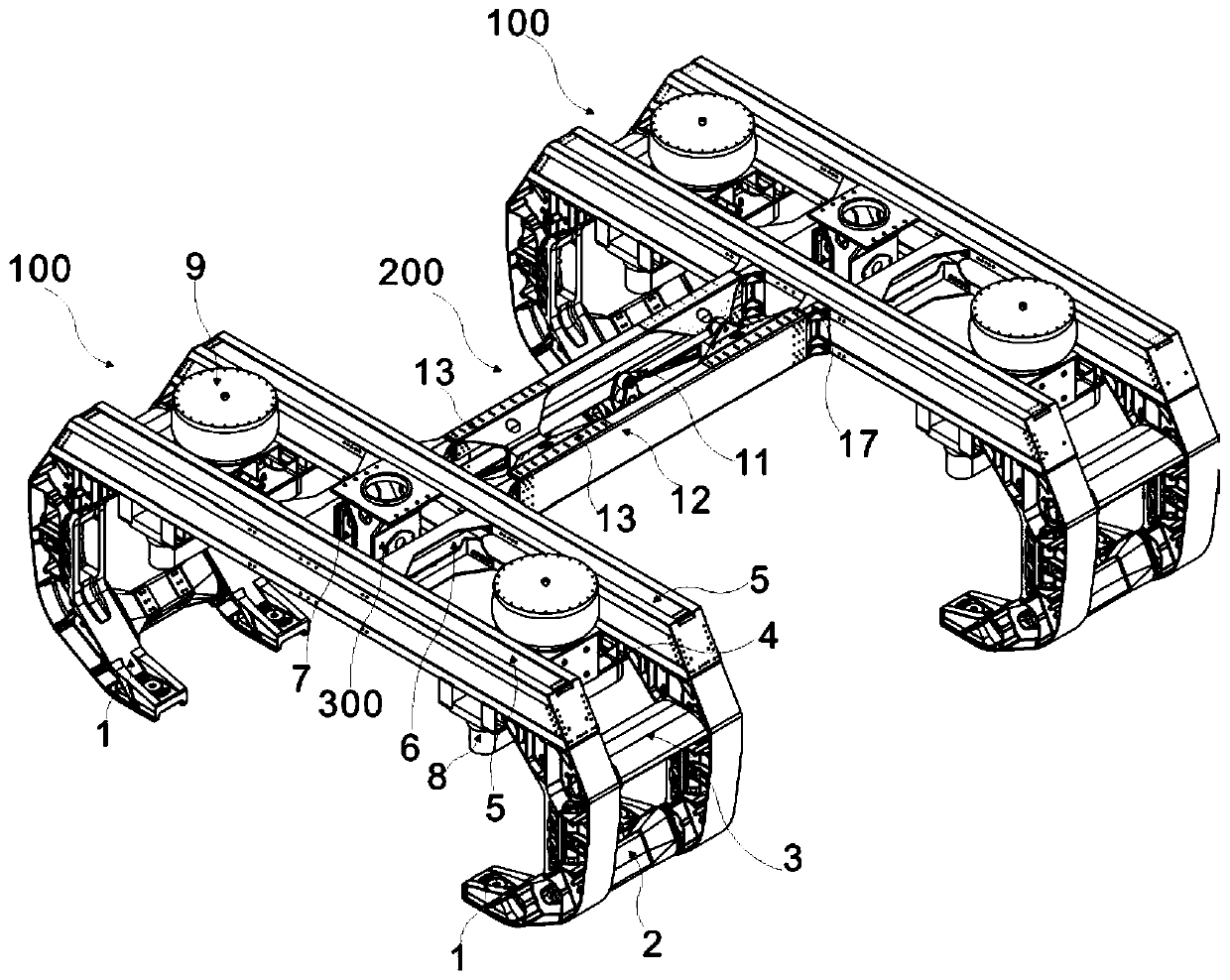
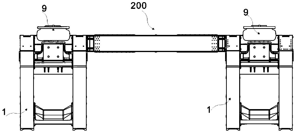
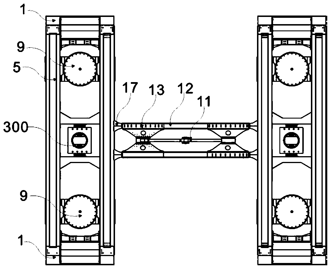
[0040] Such as figure 1 , 2 , 3 shows: a lightweight high-speed maglev vehicle running gear device, including a main longitudinal beam unit 200 and two suspension frame units 100 connected to it.

[0041] Among them, the suspension frame unit 100 is mainly composed of the electromagnet support arm 1, the lower connecting piece of the support arm 2, the upper connecting piece 3 of the support arm, the air spring mounting beam 4, the main beam 5, the transverse stop mounting beam 6, and the transverse stop mounting seat. It is composed of 7 parts, and the parts on the suspension frame unit 100 are connected by high-strength bolts. Specifically, there are four electromagnet support arms, each of which is a set of two, each of which is connected by the upper connecting member 3 of the support arm and the lower connecting member 2 of the support arm, and then connected with the two ends of the main beam 5. An air spring 9 and a lateral stop device 300 are installed on the main beam 5....


PUM

PropertyMeasurementUnit
Effective diameteraaaaaaaaaa

Abstract

The invention discloses a lightweight high-speed maglev vehicle running part device which comprises a main longitudinal beam unit and a suspension frame unit, wherein the suspension frame unit comprises electromagnet supporting arms, a transverse stopping device, an air spring and a main cross beam. The electromagnet supporting arms are arranged at two ends of the main cross beam, and the transverse stopping device and the air spring are arranged on the main cross beam and the main longitudinal beam unit comprises a Z-shaped traction pull rod device, a main longitudinal beam with enhanced decoupling capacity and a main longitudinal beam connecting beam, wherein the main longitudinal beam connecting beam is connected with the main longitudinal beam. According to the lightweight high-speed maglev vehicle running part device, the large-size air spring with the working stroke capable of meeting the line adaptability requirement of the high-speed maglev vehicle is adopted, the swing bolstermechanism formed by the parts such as a connecting seat, a swing table, a suspension rod, a swing bolster and a small-size air spring in the design scheme of the running part of the existing high-speed maglev vehicle is replaced, and the light-weight high-speed maglev vehicle running part without the swing bolster is formed. Therefore, the number of parts is reduced, assembly and maintenance arefacilitated, and reliability and economical efficiency of a secondary suspension device are improved.

Description

Technical field [0001] The invention relates to the technical field of high-speed maglev vehicles, in particular to a lightweight high-speed maglev vehicle running part device and a maglev vehicle having the running part. Background technique [0002] The running part is the most important load-bearing component of high-speed maglev vehicles, which plays an important role in support, guidance, traction and buffering. Under the premise of satisfying the above-mentioned functions, the lightweight design of the running gear is realized as much as possible, and the dynamic effect between the car and the rail is reduced, which is of great significance to improving the service life, ride comfort and energy efficiency of high-speed maglev vehicles. [0003] The existing high-speed maglev vehicle running part supports the vehicle body and provides the displacement between the vehicle body and the running part through 4 air springs. However, due to the small diameter of these air springs (3...

Claims


Application Information

Patent Timeline
IPC IPC(8): B61F5/02B61F5/10
CPCB61F5/02B61F5/10
Inventor 刘建新郭峰谢鸣赵春发朱瑞
Owner SOUTHWEST JIAOTONG UNIV
Learn More