Upper cover and washing machine
A cover body and installation groove technology, applied in the field of washing machines, can solve the problems of fast falling speed of the cover body, inconvenient use, poor safety, etc., and achieve the effects of smooth, continuous and even closing, strong operability, and simple installation.
- Summary
- Abstract
- Description
- Claims
- Application Information
AI Technical Summary
Problems solved by technology
Method used
Image
Examples
Embodiment 1
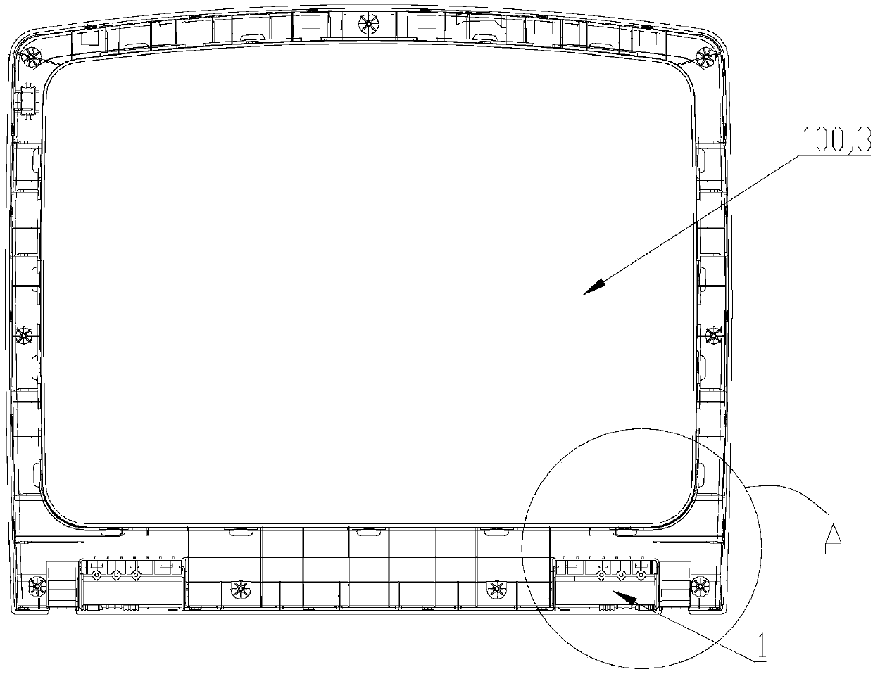
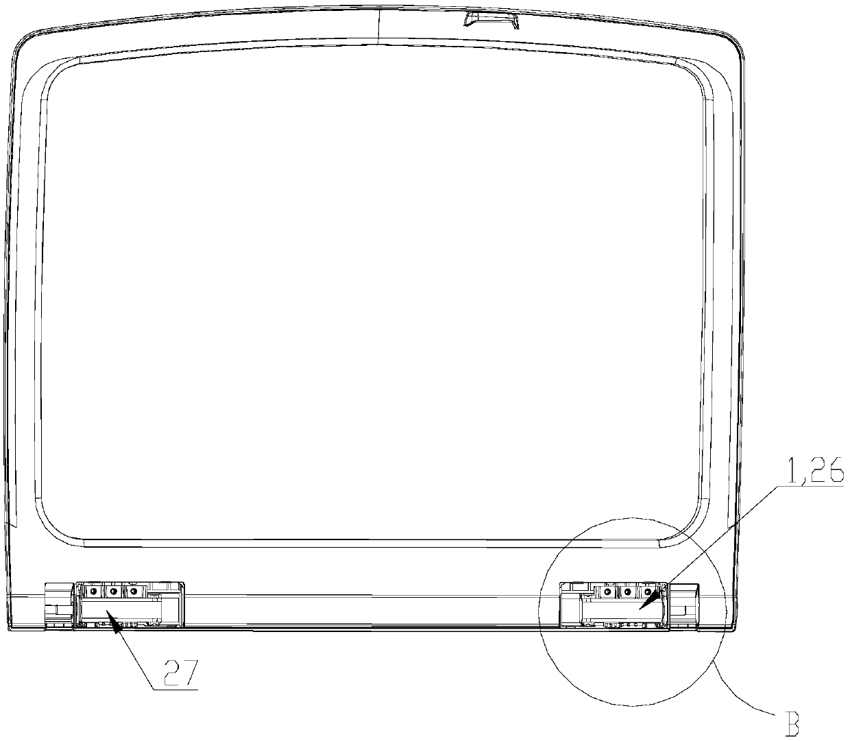
[0039] Such as Figure 1 to Figure 4 As shown, the present embodiment introduces an upper cover 100 including a cover body 3 and a damper 2 arranged on the cover body 3 , the fastening side of the cover body 3 is provided with an inwardly recessed installation groove 1 , and the installation groove 1 is installed with a damper 2, and the damper 2 is fixedly connected with the cover body 3 through the connection structure 5. By setting the damper on the upper cover, the cover body can be prevented from falling rapidly, and the cover body can be closed smoothly, continuously and evenly. At the same time, by setting the connection structure in the installation groove, part of the shell of the damper is clamped by the limit rib Hold in the installation groove to achieve the purpose of further fixing the damper.
[0040] In this embodiment, the installation groove 1 is arranged on the fastening side of the cover body 3 and is located on the outer peripheral portion of one side of ...
Embodiment 2
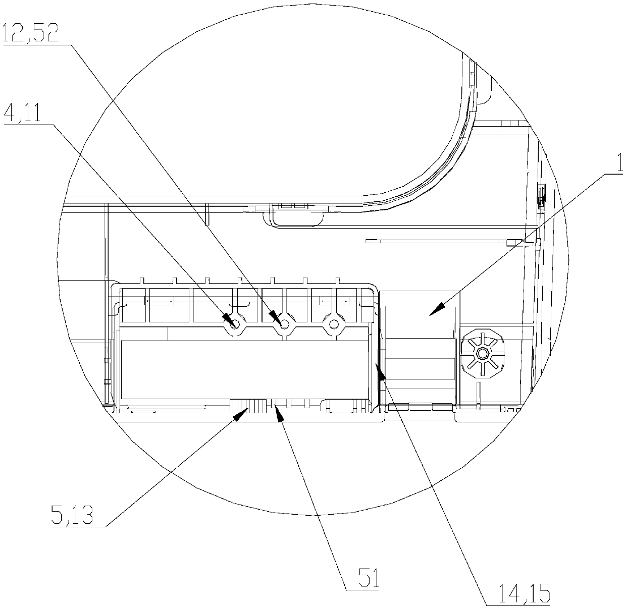
[0046] Such as Figure 1 to Figure 4 As shown, in this embodiment, a damper 2 is installed in the installation groove 1, and the damper 2 is fixedly connected to the cover body 3 through the connecting structure 5. The connecting structure 5 includes a first connecting structure 51 and a second connecting structure 52, and the damping The housing 21 of the device 2 is installed in the installation groove 1 through the first connection structure 51 and the second connection structure 52 , and is fixedly connected with the cover body 3 . The second connection structure 52 in the installation groove includes a screw column 11, and the screw column 11 and the damper housing 21 are respectively provided with corresponding installation holes 4, and the connectors pass through the installation holes 4 in order to fix the damper 2. in mounting slot 1.
[0047] In this embodiment, a screw column 11 protruding from the bottom of the groove to the notch is provided in the installation g...
Embodiment 3
[0051] Such as Figure 1 to Figure 4 As shown, in this implementation, the damper 2 also includes a housing 21 and a damping shaft 22 inserted into the housing 21. The damping shaft 22 protrudes outward from one end of the housing 21, and the extension direction of the damping shaft 22 is consistent with the mounting groove. 1 are parallel to the extending direction, and the mounting groove 1 is provided with a shaft hole 14 for the damping shaft 22 to pass through. The concrete structure and working principle of damper 2 etc. are prior art, no longer describe in detail here.
[0052] In this embodiment, the damping shaft 22 extends away from the center of the cover body 3 .
[0053] In the present embodiment, the installation groove 1 is provided with the installation rib 15 perpendicular to the extension direction of the installation groove 1, and the installation rib 15 is fixedly connected with the inner walls on the left and right sides of the installation groove 1 exten...
PUM
 Abstract
Description
Claims
Application Information
 - R&D Engineer
- R&D Manager
- IP Professional
- Industry Leading Data Capabilities
- Powerful AI technology
- Patent DNA Extraction
Browse by: Latest US Patents, China's latest patents, Technical Efficacy Thesaurus, Application Domain, Technology Topic, Popular Technical Reports.
© 2024 PatSnap. All rights reserved.Legal|Privacy policy|Modern Slavery Act Transparency Statement|Sitemap|About US| Contact US: help@patsnap.com


