Convenient-to-move rebar cutting machine

A cutting machine and steel bar technology, which is applied in the field of steel bar cutting, can solve the problems of easy displacement of steel bars, inaccurate cutting, and laborious movement, etc., and achieve the effect of reasonable structure, convenient cutting and simple operation

Active Publication Date: 2020-02-28
河源东江电力线路器材有限公司
View PDF12 Cites 1 Cited by
  • Summary
  • Abstract
  • Description
  • Claims
  • Application Information

AI Technical Summary

Problems solved by technology

[0004] Based on the background technology, existing steel bar cutting machines are relatively heavy in weight, and it is difficult to move, and when cutting steel bars, the steel bars are prone to displacement, resulting in inaccurate cutting technical problems. The present invention proposes a steel bar that is easy to move Cutting Machine

Method used


Image

  • Convenient-to-move rebar cutting machine
  • Convenient-to-move rebar cutting machine
  • Convenient-to-move rebar cutting machine

Examples


Embodiment 1

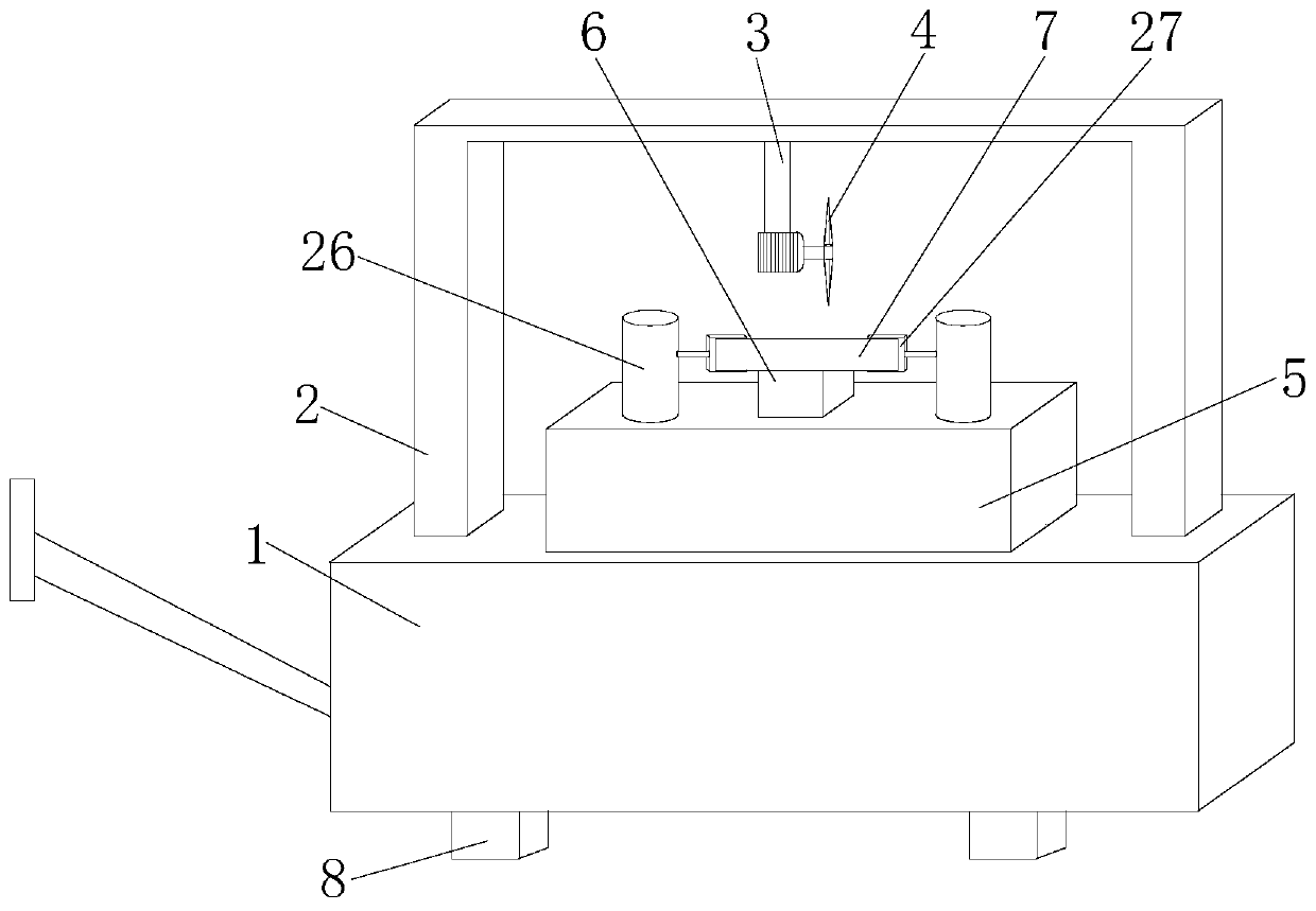
[0026] refer to Figure 1-5 In this embodiment, a steel bar cutting machine that is easy to move is proposed, which includes a base 1, a handle is fixedly connected to one side of the base 1, a fixed frame 2 is fixedly connected to the top of the base 1, and a fixed frame 2 is fixedly connected to the inside of the top of the fixed frame 2. There is a fixed plate 3, the bottom of the fixed plate 3 is fixedly connected with a cutting machine main body 4, the top of the base 1 is fixedly connected with a fixed seat 5, the top of the fixed seat 5 is fixedly connected with a placement plate 6, and the fixed seat 5 is provided with a drive assembly. There are two vertical boards 26 connected by transmission on the component, and the sides of the two vertical boards 26 close to each other are fixedly connected with a clamping plate 27, and the same steel bar main body 7 is clamped and fixed on the two clamping plates 27, and the base 1 The bottom is symmetrically fixedly connected w...

Embodiment 2

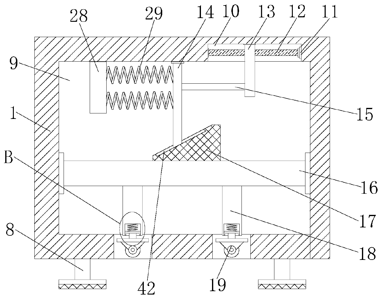
[0028] In this embodiment, the moving assembly includes a fixed chamber 9 arranged on the base 1, a mounting groove 10 is opened on the top of the fixed chamber 9, and a first motor 11 is fixedly connected to the inner wall of one side of the mounting groove 10. A rotating shaft 12 is fixedly connected to the output shaft of a motor 11, and one end of the rotating shaft 12 is rotatably connected to the other side inner wall of the mounting groove 10. The rotating plate 13 is screwed on the rotating shaft 12, and the top inner wall of the fixed chamber 9 is slidably connected to a Moving bar 14, one side of moving bar 14 is fixedly connected with fixed bar 15, and one end of fixed bar 15 is fixedly connected with one side of moving plate 13, and sliding plate 16 is slidably connected in fixed chamber 9, and the top of sliding plate 16 is fixed A swash plate 17 is connected, and the bottom of the moving rod 14 is slidingly connected to one side of the swash plate 17. The bottom o...


PUM


Abstract

The invention belongs to the field of rebar cutting, particularly relates to a convenient-to-move rebar cutting machine, and aims to solve the problems that some of the existing rebar cutting machinesare heavier and more strenuous to move, and rebars are likely to have displacement during the rebar cutting process. According to the scheme, the convenient-to-move rebar cutting machine comprises abase, wherein a handle is fixedly connected with one side of the base; a fixed rack is fixedly connected with the top of the base; a fixed plate is connected with the top interior of the fixed rack; acutting machine main body is connected with the bottom of the fixed plate; a fixed seat is connected with the top of the base; a placing plate is connected with the top of the fixed seat; a driving component is arranged on the fixed seat; two vertical plates are in transmission joint with the driving component; and clamping plates are connected with two sides mutually close to each other of the two vertical plates. The convenient-to-move rebar cutting machine is reasonable in structure and simple to operate to move a cutting machine main body, so that application by a user is facilitated; anda second motor is adopted to clamp and fix the rebar main body, so that during the cutting process, the rebar main body does not move and cutting is not affected.

Description

technical field [0001] The invention relates to the technical field of steel bar cutting, in particular to a mobile steel bar cutting machine. Background technique [0002] Steel bar refers to steel for reinforced concrete and prestressed reinforced concrete. The straight or coiled steel used for reinforcement has two shapes: smooth round steel bar and deformed steel bar. The delivery state is straight bar and coiled steel bar. In the process of steel bar processing, the cutting of steel bar is also a very important step. process. [0003] Some of the existing steel bar cutting machines are relatively heavy, and it is difficult to move, and when cutting steel bars, the steel bars are prone to displacement, resulting in inaccurate cutting. Therefore, we propose a mobile steel bar cutting machine to solve the above problems. The problem. Contents of the invention [0004] Based on the background technology, existing steel bar cutting machines are relatively heavy in weigh...

Claims


Application Information

Patent Timeline
IPC IPC(8): B21F11/00
CPCB21F11/00
Inventor 谢洁萍
Owner 河源东江电力线路器材有限公司
Why Eureka
Try Eureka