Gynecological operation sickbed

A technology for obstetrics and gynecology and surgery, applied in the field of surgical beds, can solve problems such as inconvenience of use, splashing blood on the ground, and difficulty in cleaning, and achieve the effects of being convenient to use, convenient for applying force, and helpful for childbirth

Inactive Publication Date: 2020-02-21
杭州迪易家医疗器械有限公司
View PDF0 Cites 1 Cited by
  • Summary
  • Abstract
  • Description
  • Claims
  • Application Information

AI Technical Summary

Problems solved by technology

[0004] The object of the present invention is to provide an obstetrics and gynecology surgery bed to solve the above-mentioned background technology. The blood receiving basin of the existing obstetrics and gynecology surgery bed is directly placed under the delivery bed. This placement method is very inconvenient to use. Because there is a large gap with the delivery bed, the blood left behind may splash on the ground, causing problems that are difficult to clean up later

Method used


Image

  • Gynecological operation sickbed
  • Gynecological operation sickbed
  • Gynecological operation sickbed

Examples


Embodiment 1

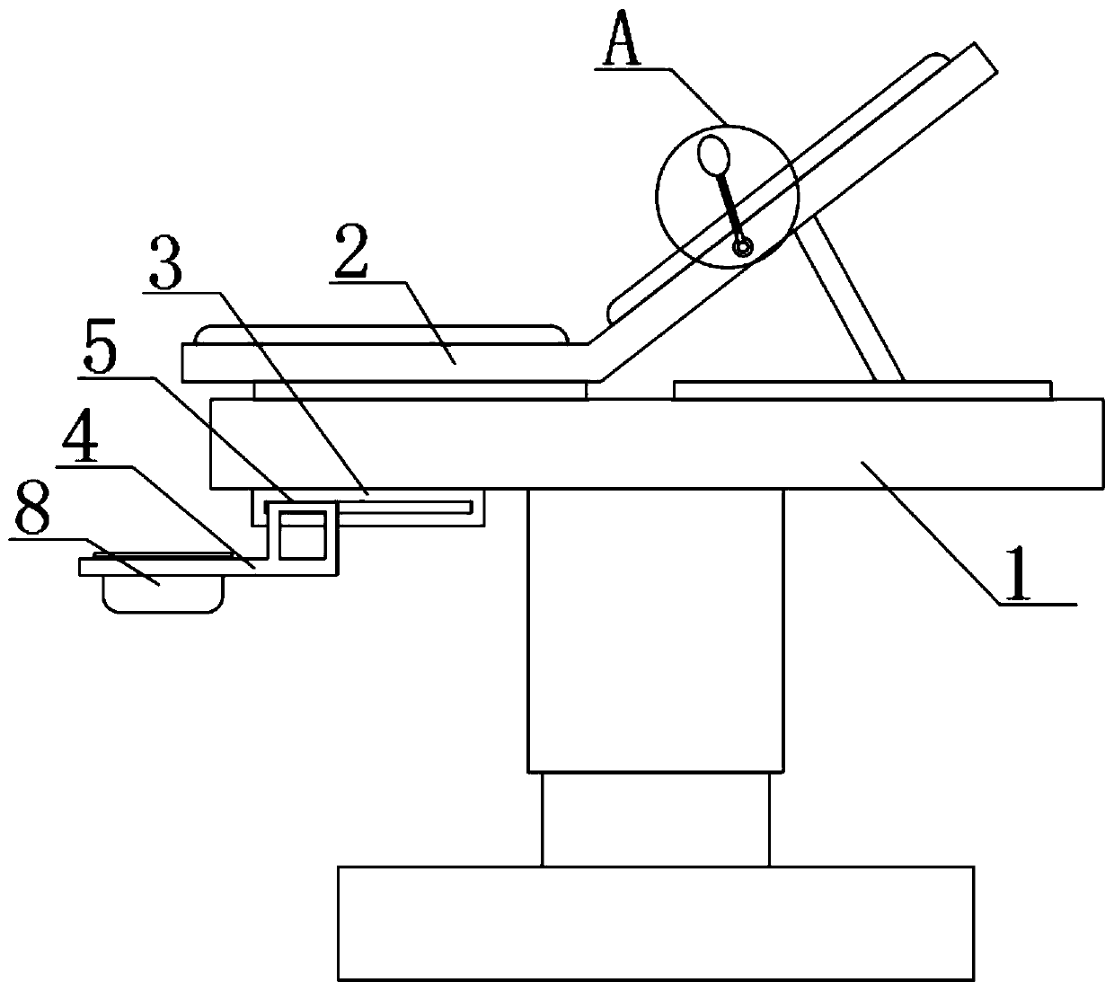
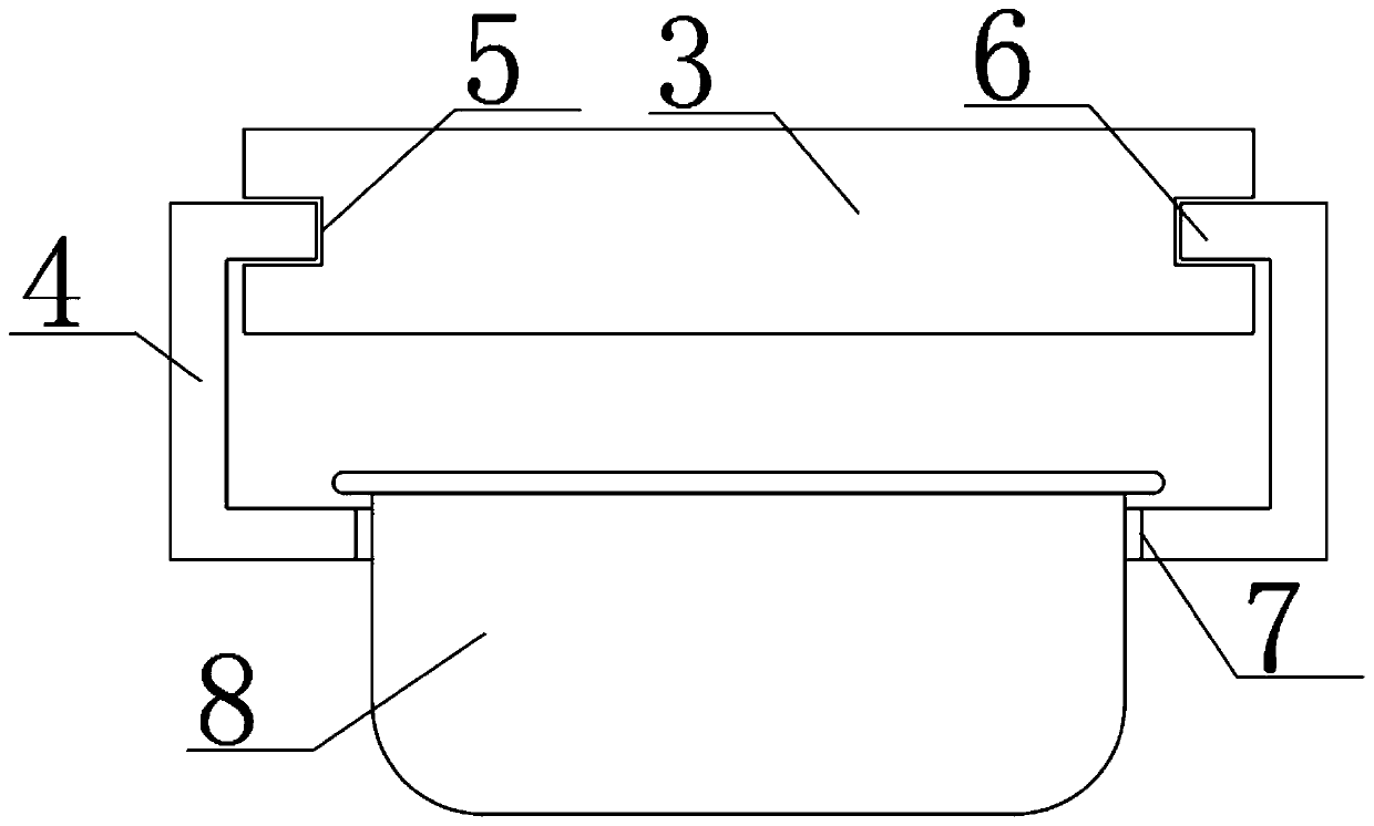
[0021] See figure 1 with figure 2 , The present invention provides a technical solution: the obstetrics and gynecology surgical bed includes a lifting platform 1, the top of the lifting platform 1 is provided with a delivery bed 2, the bottom of the lifting platform 1 is fixed with a fixed block 3, and the bottom of the fixed block 3 is provided with a fixed Piece 4, the two sides of the fixing block 3 are symmetrically provided with sliding grooves 5, the end of the fixing piece 4 is symmetrically fixed with a sliding block 6, the sliding block 6 is connected with the sliding groove 5, and the surface of the fixing piece 4 is penetrated with a through groove 7. The blood receiving basin 8 is placed inside the penetrating groove 7. The designed structure of the present invention allows the obstetrics and gynecology surgical bed to pass through the designed fixing block 3, fixing piece 4, sliding groove 5, and sliding block 6 when in use. The penetrating groove 7 is easily and q...

Embodiment 2

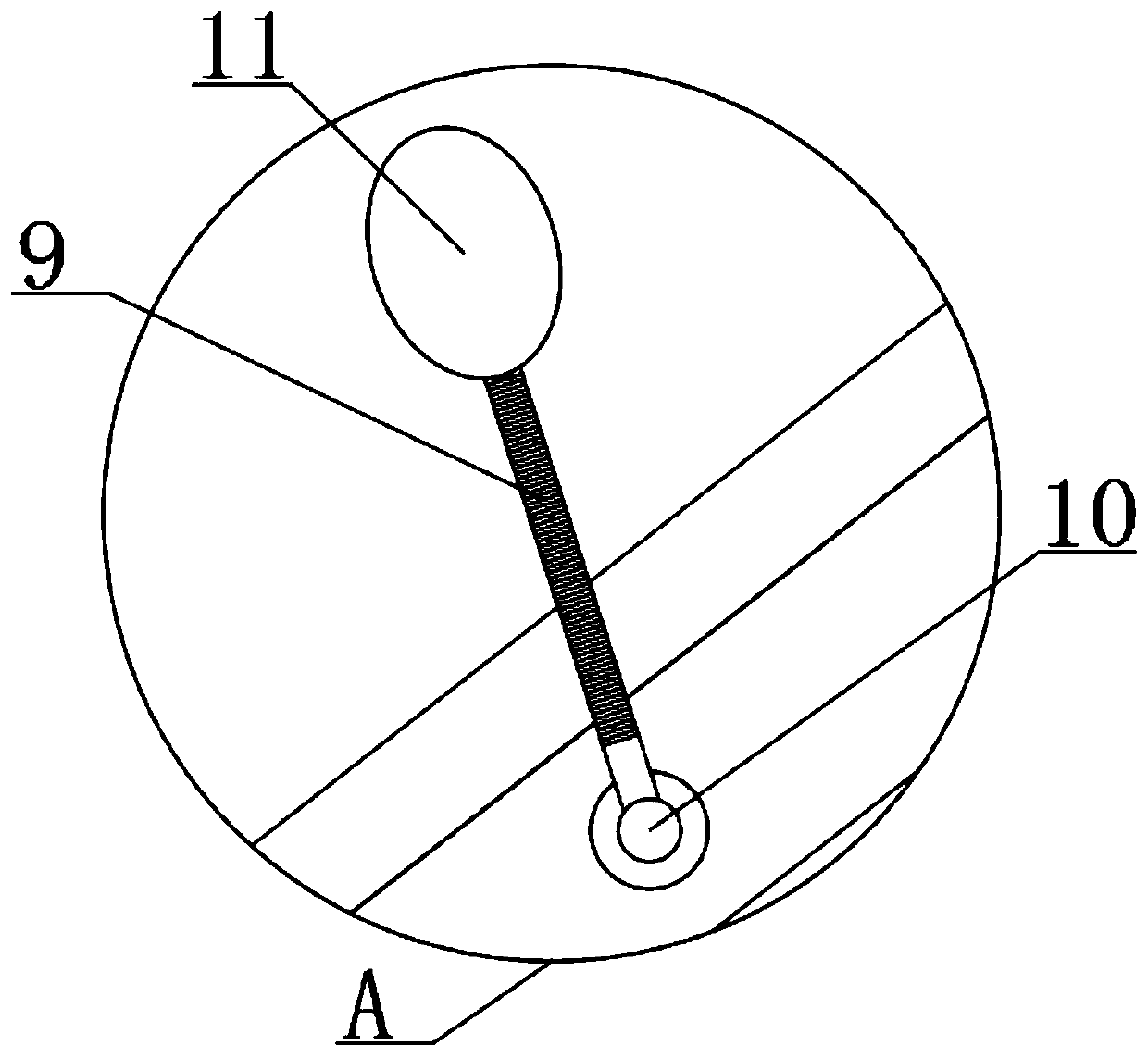
[0023] See Figure 1 to Figure 3 , The present invention provides a technical solution: the obstetrics and gynecology surgical bed includes a lifting platform 1, the top of the lifting platform 1 is provided with a delivery bed 2, the bottom of the lifting platform 1 is fixed with a fixed block 3, and the bottom of the fixed block 3 is provided with a fixed Piece 4, the two sides of the fixing block 3 are symmetrically provided with sliding grooves 5, the end of the fixing piece 4 is symmetrically fixed with a sliding block 6, the sliding block 6 is connected with the sliding groove 5, and the surface of the fixing piece 4 is penetrated with a through groove 7. The blood receiving basin 8 is placed inside the penetrating groove 7. The designed structure of the present invention allows the obstetrics and gynecology surgical bed to pass through the designed fixing block 3, fixing piece 4, sliding groove 5, and sliding block 6 when in use. The penetrating groove 7 is easily and qu...


PUM


Abstract

The invention discloses a gynecological operation sickbed. The sickbed comprises a lifting table, an obstetric table is arranged at the top of the lifting table, a fixing block is fixed to the bottomof the lifting table, a fixing piece is arranged at the bottom of the fixing block, sliding grooves are symmetrically formed in the two sides of the fixing block, sliding blocks are symmetrically fixed to the ends of the fixing piece, the sliding blocks are connected to the sliding grooves in a clamped mode, a penetrating groove is formed in the surface of the fixing piece in a penetrating mode, and a blood receiving basin is placed in the penetrating groove. By means of the designed structure, when the gynecological operation sickbed is used, the blood receiving basin can be conveniently andrapidly pulled out of the bottom of the obstetric table and fixed below the obstetric table through the designed fixing block, fixing piece, sliding grooves, sliding blocks and penetrating groove, andcompared with the prior art, the use of the blood receiving basin is greatly facilitated.

Description

Technical field [0001] The invention belongs to the technical field of surgical beds, and specifically relates to surgical beds for obstetrics and gynecology. Background technique [0002] The obstetrics and gynecology surgical bed is a bed that can be used for sitting and lying, and can be used for natural childbirth, caesarean section, and gynecological examination. [0003] The existing gynecology and obstetric surgery beds still have some shortcomings in use: the blood receiving basin of the existing gynecology and obstetric surgery beds is directly placed under the delivery bed. This placement method is very inconvenient to use because There is a large gap with the delivery bed, and the remaining blood may splash on the ground, making it difficult to clean up later. Summary of the invention [0004] The purpose of the present invention is to provide a surgical bed for obstetrics and gynecology, so as to solve the problem that the blood receiving basin of the surgical bed for o...

Claims


Application Information

Patent Timeline
Patent Type & Authority Applications(China)
IPC IPC(8): A61G13/08A61G13/06A61G13/10
CPCA61G13/0009A61G13/06A61G13/08A61G13/10A61G13/102A61G2200/12
Inventor 王洪根
Owner 杭州迪易家医疗器械有限公司
Why Eureka
Try Eureka