
Terminal equipment

A technology for terminal equipment and earpieces, which is applied to instruments, electrical digital data processing, digital data processing components, etc., can solve the problems of not enough beauty, not enough sound holes, and high cost of touch screen

Pending Publication Date: 2020-02-14
MEIZU TECH CO LTD
View PDF5 Cites 2 Cited by
  • Summary
  • Abstract
  • Description
  • Claims
  • Application Information

AI Technical Summary

Problems solved by technology

[0002] Existing terminal equipment usually sets the sound outlet of the earpiece at the front of the device. As the terminal equipment enters the era of full screen, the front shell frame above the touch screen of the terminal equipment becomes narrower and narrower, resulting in insufficient space for the upper frame to set the sound hole. , in order to solve the above problems, there are currently two design schemes adopted. One scheme is to partially widen the upper frame, so that the upper frame partially forms a downwardly protruding protrusion, and sets and protrudes on the corresponding position of the touch screen. The groove that fits the inside, and the sound hole is set on the protrusion of the upper frame, but this setting destroys the integrity of the appearance of the touch screen, which is not beautiful enough
Another solution is to set the sound hole on the touch screen, but the cost of the touch screen is high, so that the production cost of the product increases

Method used


Image

  • Terminal equipment
  • Terminal equipment

Examples


Embodiment Construction

[0031] In order to understand the above-mentioned purpose, features and advantages of the present invention more clearly, the present invention will be further described in detail below in conjunction with the accompanying drawings and specific embodiments. It should be noted that, in the case of no conflict, the embodiments of the present application and the features in the embodiments can be combined with each other.

[0032] In the following description, many specific details are set forth in order to fully understand the present invention. However, the present invention can also be implemented in other ways than described here. Therefore, the protection scope of the present invention is not limited by the specific implementation disclosed below. Example limitations.

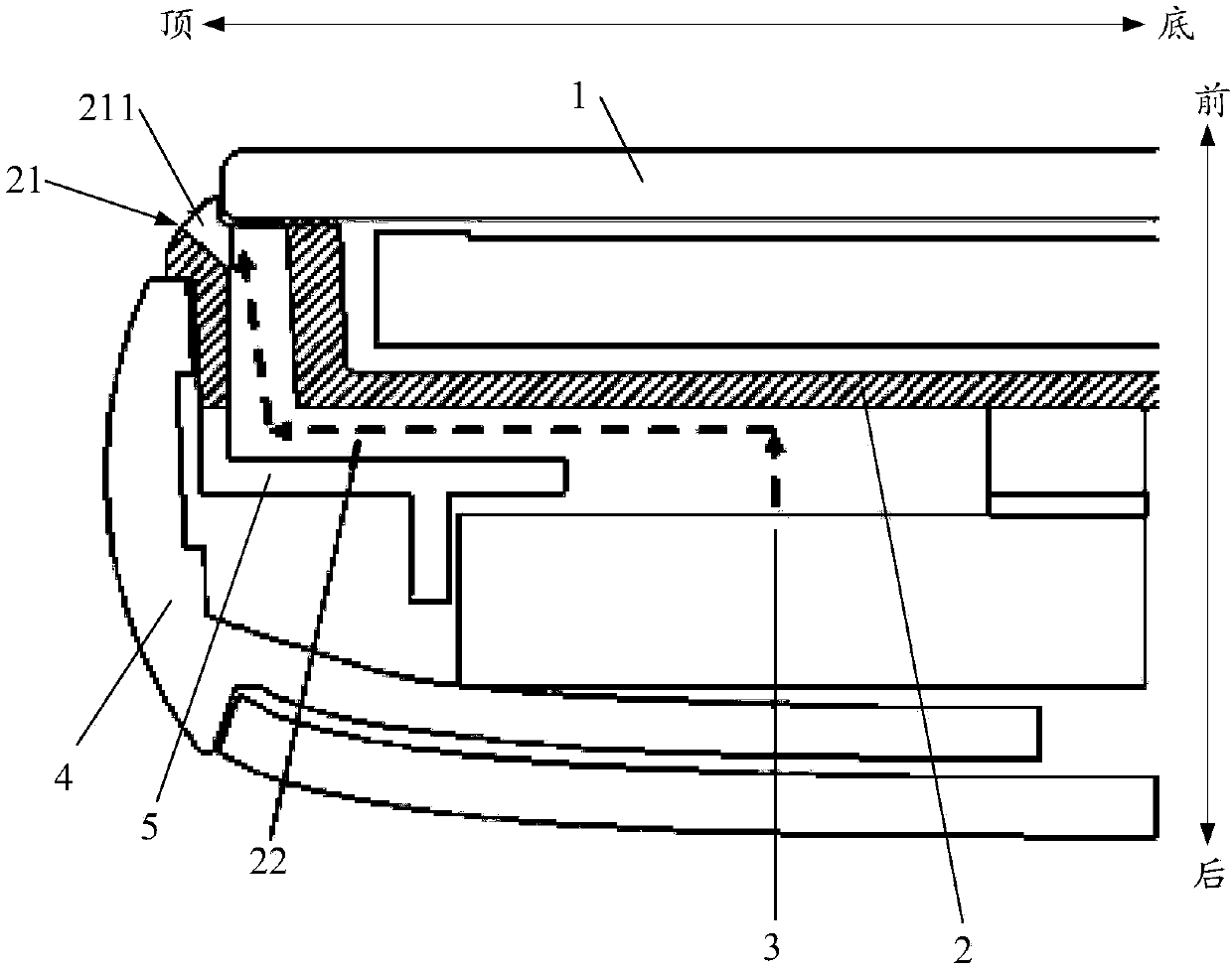
[0033] Embodiments of the present invention provide a terminal device, such as figure 1 and figure 2 As shown, the terminal device includes: a touch screen 1, a front case 2, a handset 3 and a rear cover 4...


PUM


Abstract

The invention provides terminal equipment. The equipment comprises a touch screen, a front shell and an earphone body, the touch screen is installed on the front side of the front shell, the earphonebody is installed on the rear side of the front shell, an inclined plane or a curved surface facing the upper front portion is formed on the top surface of the front shell, a sound outlet hole is formed in the inclined plane or the curved surface, and the sound outlet hole is communicated with a sound outlet of the earphone body. According to the scheme, the sound outlet hole is formed in the topsurface of the front shell, and sound is emitted from the side part of the terminal equipment, so that the top frame of the touch screen can be reduced to the greatest extent, the integrity of the touch screen cannot be damaged, the product is more attractive, the sound outlet hole does not need to be formed in the touch screen, the touch screen is low in manufacturing cost, and the production cost of the product can be reduced. According to the scheme, the sound outlet hole is formed in the inclined surface or the curved surface, so that the area of the sound outlet hole is large enough, andthe sound transmitted by the sound outlet hole is clear enough.

Description

technical field [0001] The present invention relates to the field of communication equipment, and more specifically, to a terminal equipment. Background technique [0002] Existing terminal equipment usually sets the sound outlet of the earpiece at the front of the device. As the terminal equipment enters the era of full screen, the front shell frame above the touch screen of the terminal equipment becomes narrower and narrower, resulting in insufficient space for the upper frame to set the sound hole. , in order to solve the above problems, there are currently two design schemes adopted. One scheme is to partially widen the upper frame, so that the upper frame partially forms a downwardly protruding protrusion, and sets and protrudes on the corresponding position of the touch screen. The groove that fits the inside, and the sound hole is set on the protrusion of the upper frame, but this setting destroys the integrity of the appearance of the touch screen, which is not beau...

Claims


Application Information

Patent Timeline
IPC IPC(8): G06F1/16
CPCG06F1/1626G06F1/1688
Inventor 程武黄国钊吴志龙
Owner MEIZU TECH CO LTD
Learn More