
Shunt body device and air conditioner

An air-conditioning and shunting technology, which is applied in the direction of fluid circulation arrangement, refrigeration components, refrigerators, etc., can solve the problems of opaque shunt body, inconvenient analysis of the fluid flow pattern and distribution of the shunt body, and improve authenticity and accuracy Sexuality, observation and intuitive effect

Inactive Publication Date: 2020-02-07
NINGBO AUX ELECTRIC
View PDF4 Cites 0 Cited by
  • Summary
  • Abstract
  • Description
  • Claims
  • Application Information

AI Technical Summary

Problems solved by technology

[0004] The problem solved by the invention is that the existing shunt body is opaque, and it is inconvenient to analyze the fluid flow pattern and distribution in the shunt body

Method used


Image

  • Shunt body device and air conditioner
  • Shunt body device and air conditioner
  • Shunt body device and air conditioner

Examples


Embodiment Construction

[0033] In the branch body in the prior art, in order to facilitate the observation of the flow pattern and distribution of the fluid, a visualization window is generally set on the branch body. The high temperature and high pressure sealing between different materials between the shunt body and the visualization window is complicated.

[0034] In order to make the above objects, features and advantages of the present invention more comprehensible, specific embodiments of the present invention will be described in detail below in conjunction with the accompanying drawings.

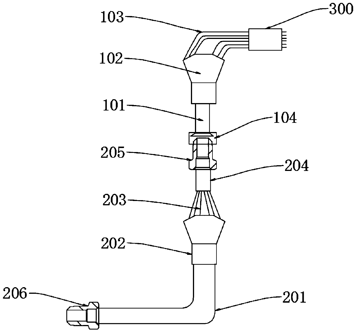
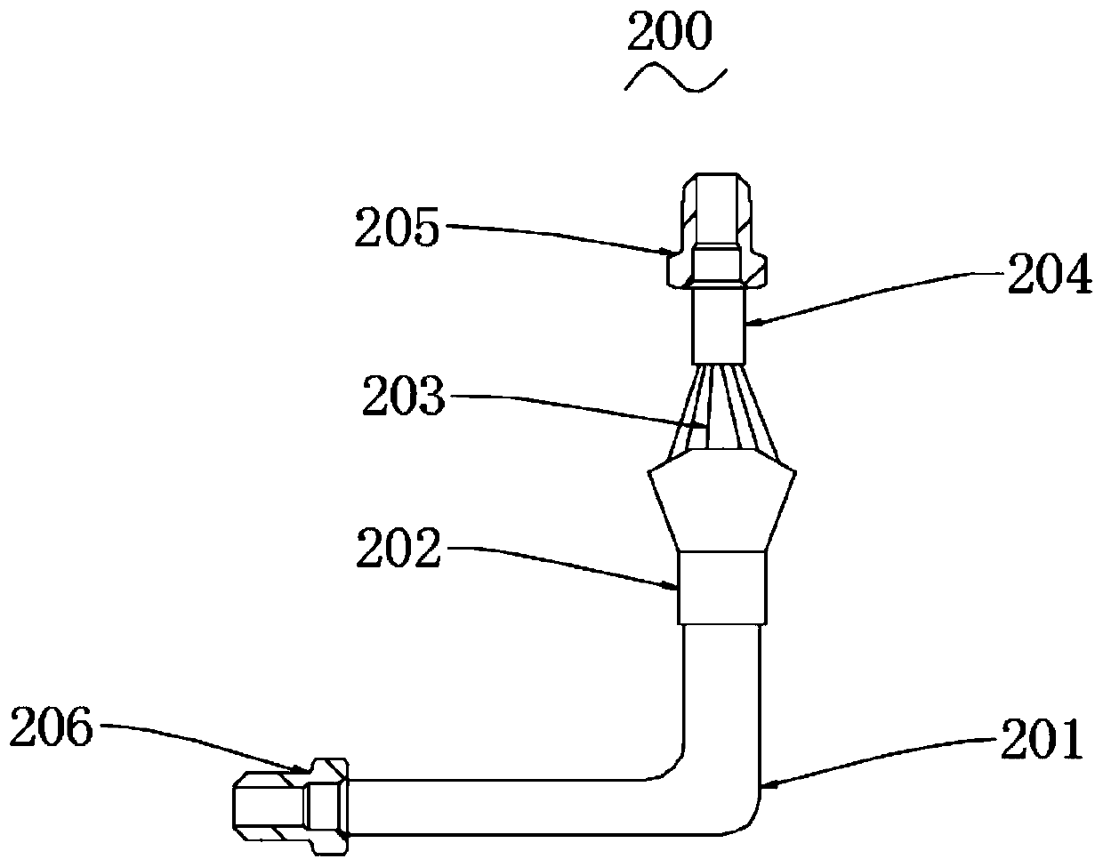
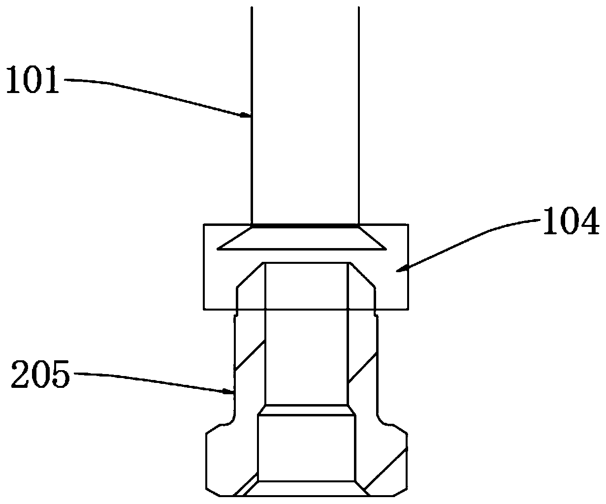
[0035] see figure 1 As shown, the embodiment of the present invention provides a branch body device 200 , which is made of transparent material and is suitable for being installed in front of the air-conditioning liquid distribution pipe assembly 100 .

[0036] In this embodiment, a transparent and visualized branch body device 200 is installed in front of the air conditioner liquid distribution pipe assem...


PUM


Abstract

The invention provides a shunt body device and an air conditioner. The shunt body device is made of transparent materials and is suitable for being installed in front of a liquid distribution pipe assembly of the air conditioner. The visual shunt body device is arranged in front of the liquid distribution pipe assembly of the air conditioner, and the flow state and distribution condition of refrigerants in the liquid distribution pipe assembly of the air conditioner are simulated through the fluid flow type and the liquid level observed in the shunt body device, so that the research on the fluid form, the liquid level and the like in the liquid distribution pipe assembly of the air conditioner in the air conditioner development stage is facilitated, and thus components such as a liquid distribution head with better liquid distribution, a liquid inlet pipe with proper curvature and a shunt capillary pipe can be developed. In addition, the whole visual shunt body device is made of transparent materials, and observation is more intuitive and convenient.

Description

technical field [0001] The invention relates to the technical field of air conditioning, in particular to a branch body device and an air conditioner. Background technique [0002] In the air conditioner, since there are many pipelines connecting the internal and external units, in order to reduce the flow and pressure loss, the refrigerant needs to be divided into multiple branches, which will cause the refrigerant flow in each branch to be different. In order to solve the refrigerant flow distribution Generally, the shunt body assembly will be installed in the pipeline. [0003] However, the conventional shunt body in the prior art is mainly made of metal, because the state of the gas-liquid two-phase refrigerant in the shunt body can be divided into various flow types, including slug flow, bubbly flow, and stratified flow. Fluids of different flow patterns will have different effects on the consistency of liquid separation and the sound of liquid flow, so it is difficult...

Claims


Application Information

Patent Timeline
IPC IPC(8): F25B41/00F25B41/40
CPCF25B41/00
Inventor 袁封明王义祥易忠衍谢斌王成
Owner NINGBO AUX ELECTRIC
Learn More