
Relative position adjustment system for vehicle body

A relative position and adjustment system technology, applied in the direction of measuring devices, optical devices, instruments, etc., can solve the problems of laser component angle error, unsatisfactory adjustment effect, and low measurement accuracy, so as to improve efficiency, reduce operation steps, and achieve high efficiency. The effect of precision

Active Publication Date: 2020-02-07
烟台开发区海德科技有限公司
View PDF8 Cites 6 Cited by
  • Summary
  • Abstract
  • Description
  • Claims
  • Application Information

AI Technical Summary

Problems solved by technology

The disadvantages are: (1) The operation is cumbersome, the efficiency is very low, and the work intensity is high; (2) The diameter of the laser spot itself is about 5mm, and the laser component itself also has an angle error, so the measurement accuracy is low and the adjustment effect is not ideal

Method used


Image

  • Relative position adjustment system for vehicle body
  • Relative position adjustment system for vehicle body
  • Relative position adjustment system for vehicle body

Examples


Embodiment Construction

[0038] The technical scheme of the present invention is described in detail below in conjunction with accompanying drawing:

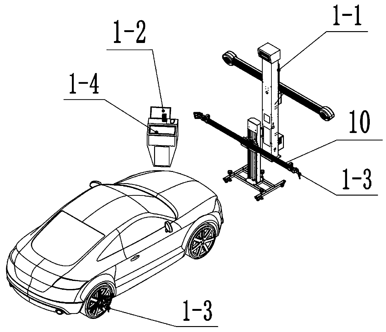
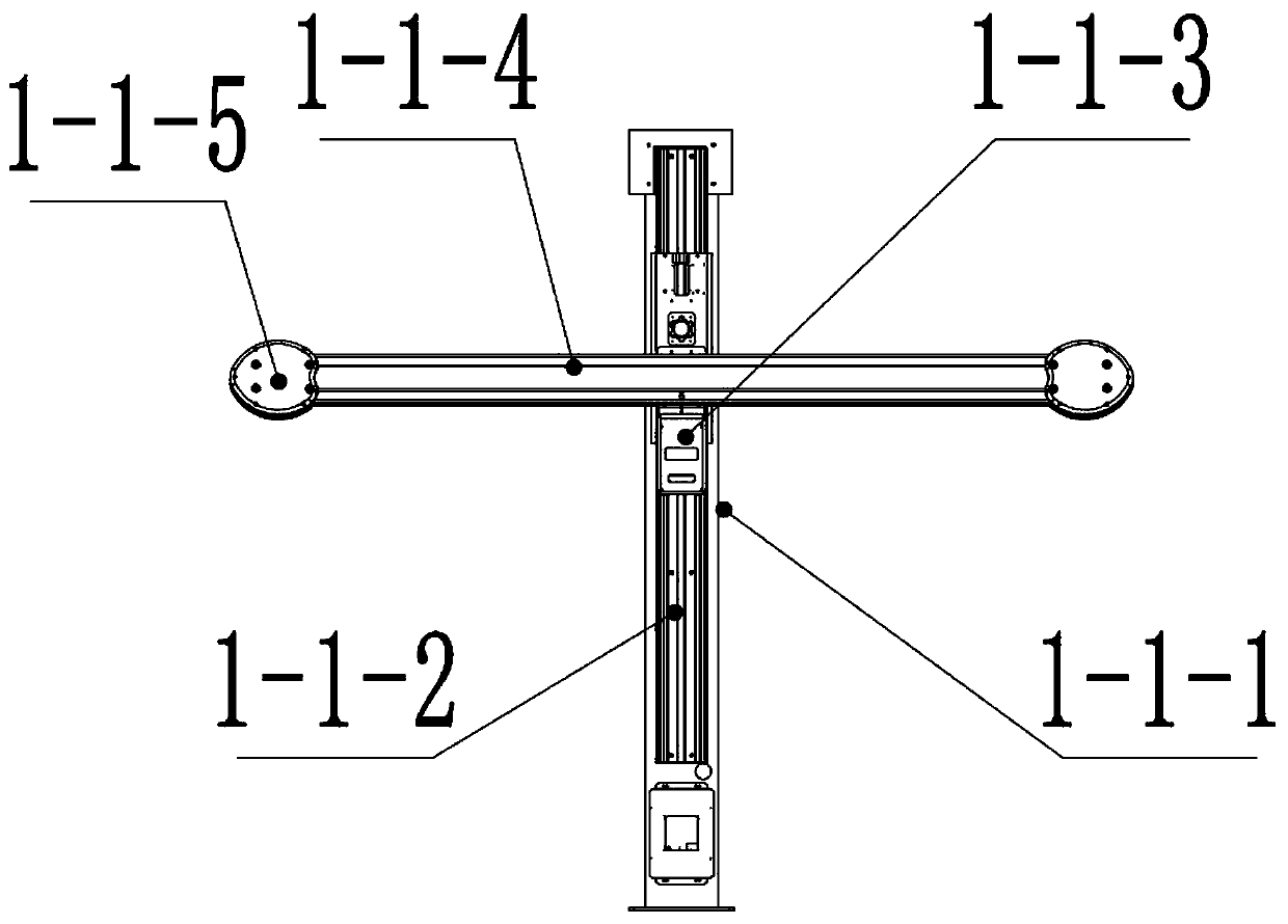
[0039] Such as figure 1 , a relative position adjustment system of an automobile body, comprising a measuring device for measuring the relative position between a calibration beam 10 and the vehicle body and a remote-control straightening device for adjusting the position and angle of the calibration beam 10 .

[0040] The invention applies the 3D measurement technology to the position measurement of the ADAS calibration system. 3D measurement technology mainly adopts the basic principles of physical perspective, computer information processing technology, and digital image recognition technology. Digital CCD cameras are used to collect image information on the target. The computer can scan the position and angle of the target to scan any target. Coordinate values ​​can be obtained, and the accuracy can reach + / -0.01mm.

[0041] The calibration of auto...


PUM


Abstract

The invention discloses a relative position adjustment system for a vehicle body. The relative position adjustment system comprises a measurement body which is used for measuring the relative positionbetween a calibration beam and the vehicle body and a remote-control-type straightening device which is used for adjusting the position and angle of the calibration beam; during adjustment, an operator remotely controls the straightening device to move according to the relative position between the calibration beam and the vehicle body obtained by the measurement device until the position of thecalibration beam meets the requirement. According to the relative position adjustment system, a 3D measurement technology and a remote control adjustment technology are integrated, a 3D measurement device can quickly and automatically obtain the relative position between the calibration beam and a vehicle rear axle, after seeing the position, the operator can directly adjust the height, the horizontal position and the swinging angle of the calibration beam through remote control, and judge whether or not adjustment is reasonable and proper according to the relative position information which is measured in real time, thus repeated reading and adjustment are omitted, the working efficiency is significantly improved, and the labor intensity is lowered.

Description

technical field [0001] The invention relates to a system for adjusting the relative position between an automobile body and a calibration beam. Background technique [0002] At present, more and more cars are equipped with ADAS calibration system. In the ADAS calibration system, calibration instruments such as ACC sensor calibration instrument, LDW pattern data identification board and night vision device are all installed on the calibration beam. The prerequisite for the correct calibration of the above-mentioned instruments is that there must be a correct relative position between the instrument and the vehicle body. Such as Figure 15 , so the first step of the ADAS calibration system is to place the calibration device in a position aligned with the vehicle body, and the following conditions should be met: (1) The distances L1 and L2 between the two ends of the calibration beam and the axis of the rear wheel are equal ;(2) The vertical centerline of the calibration beam...

Claims


Application Information

Patent Timeline
Patent Type & Authority Applications(China)
IPC IPC(8): B23P19/10G01B11/00
CPCB23P19/10G01B11/00
Inventor 陈德昱曲庆达张念坤宋立国张玉华董彦波刘亮商洪美胡霖于博丁培波迟艳艳
Owner 烟台开发区海德科技有限公司
Learn More