Flexible battery and preparation method thereof
A flexible battery and collector technology, applied in the field of battery energy storage, can solve problems such as difficult process, achieve the effects of improving production efficiency, facilitating integrated applications, and simple structure and production process
- Summary
- Abstract
- Description
- Claims
- Application Information
AI Technical Summary
Problems solved by technology
Method used
Image

Examples
preparation example Construction
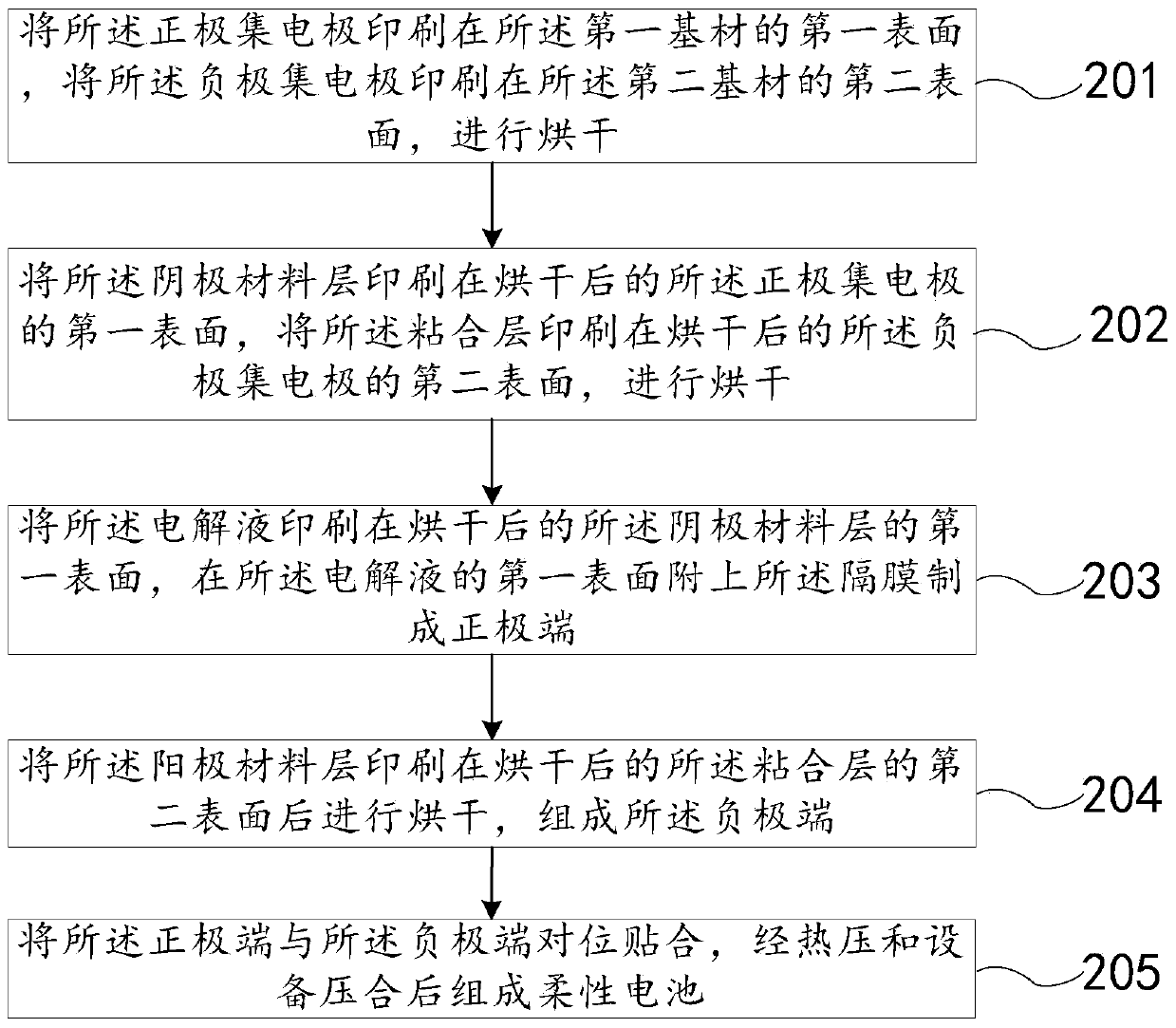
[0037] Such as figure 2 Shown, a kind of preparation method of flexible battery comprises:
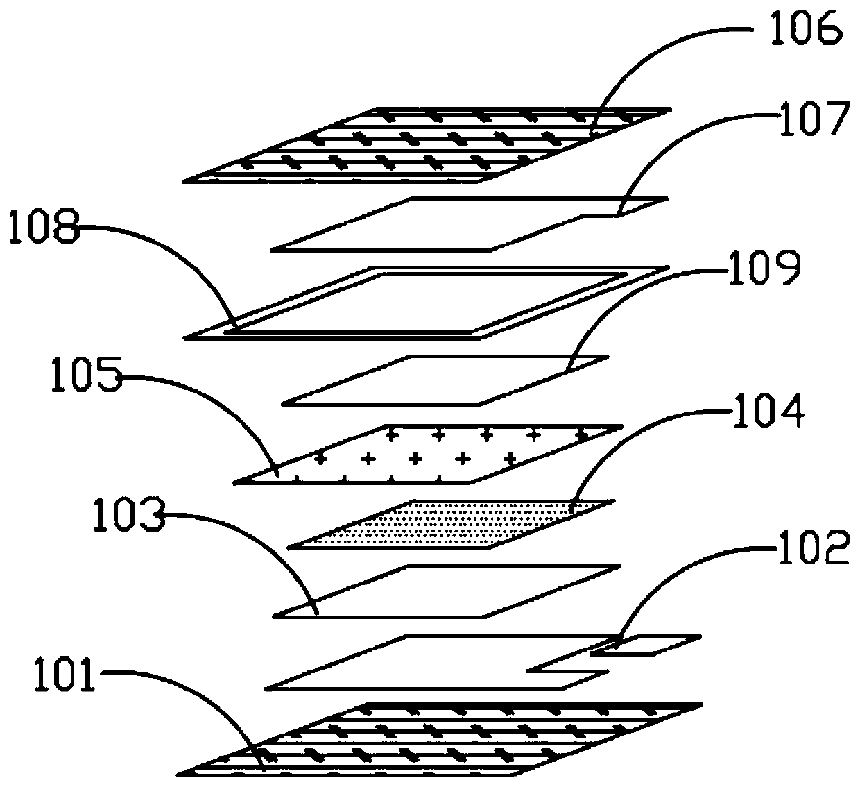
[0038] Step 201, printing the positive electrode collector 102 on the first surface of the first substrate 101, printing the negative electrode collector 107 on the second surface of the second substrate 106, and drying;
[0039] Step 202, printing the cathode material layer 103 on the first surface of the dried positive electrode collector 102, and printing the adhesive layer 108 on the second surface along the periphery of the negative electrode collector 107. drying the second surface of the substrate 106;
[0040] Step 203, printing the electrolyte layer 104 on the first surface of the dried cathode material layer 103, attaching the separator 105 on the first surface of the electrolyte layer 104 to make a positive terminal;
[0041] Step 204, printing the anode material layer 109 on the second surface of the dried negative electrode collector 107 and then drying to form the nega...
Embodiment 1
[0045] Embodiment 1, choose the conductive graphite of 40% content, the conductive carbon black of 5% content, the graphene of 0.1% content, the binding agent of 10% content mix and make positive electrode collector 102 and negative electrode collector 107, choose EVA content Make adhesive layer 108 at 20% EVA liquid hot-melt adhesive, choose the conductive carbon black of 1% content, the anode active material of 40% content, the binding agent of 10% content make anode material layer 109, choose 3% content Conductive carbon black, 40% content of cathode active material, 10% content of binder to make cathode material layer 103, select 30% content of zinc salt solution to make electrolyte layer 104, and print positive electrode collector 102 on the first substrate in turn. material 101, the cathode material layer 103 is printed on the first surface of the dried positive electrode collector 102, the electrolyte layer 104 is printed on the first surface of the dried cathode materia...
Embodiment 2
[0046] Embodiment 2, select the conductive graphite of 70% content, the conductive carbon black of 20% content, the graphene of 2% content, the binding agent of 30% content mix and make positive electrode collector 102 and negative electrode collector 107, choose EVA content Make adhesive layer 108 at 60% EVA liquid hot-melt adhesive, choose the conductive carbon black of 30% content, the anode active material of 80% content, the binding agent of 30% content make anode material layer 109, choose the anode material layer 109 of 30% content Conductive carbon black, 80% of the cathode active material, and 30% of the binder are used to make the cathode material layer 103, and 90% of the zinc salt solution is selected to make the electrolyte layer 104, and the positive electrode collector 102 is printed on the first substrate in turn. material 101, the cathode material layer 103 is printed on the first surface of the dried positive electrode collector 102, the electrolyte layer 104 ...
PUM
 Abstract
Description
Claims
Application Information
 - R&D
- Intellectual Property
- Life Sciences
- Materials
- Tech Scout
- Unparalleled Data Quality
- Higher Quality Content
- 60% Fewer Hallucinations
Browse by: Latest US Patents, China's latest patents, Technical Efficacy Thesaurus, Application Domain, Technology Topic, Popular Technical Reports.
© 2025 PatSnap. All rights reserved.Legal|Privacy policy|Modern Slavery Act Transparency Statement|Sitemap|About US| Contact US: help@patsnap.com