Positioning mechanism for trial assembly for erection of platform type power tower

A technology of positioning mechanism and power tower, applied in the direction of tower, building type, building, etc., can solve the problems of unfavorable measurement distance, lack of convenient assembly structure, inconvenient positioning of power tower, etc., and achieves less wear, simple operation, and labor consumption. small effect

Inactive Publication Date: 2020-02-04
刘 爽
View PDF0 Cites 0 Cited by
  • Summary
  • Abstract
  • Description
  • Claims
  • Application Information

AI Technical Summary

Problems solved by technology

[0006] In summary, the present invention provides a positioning mechanism for trial assembly for the erection of a platform-type power tower. Through structural and functional improvements, it solves the problem that the components of the trial assembly mechanism currently used mainly fix the tower through a fixed plate-like structure. , but it is inconvenient to locate the power tower with errors in the production process, it does not have the function of adjusting the foot position at will, it is not conducive to measuring distance, and it does not have a structure that facilitates assembly

Method used


Image

  • Positioning mechanism for trial assembly for erection of platform type power tower
  • Positioning mechanism for trial assembly for erection of platform type power tower
  • Positioning mechanism for trial assembly for erection of platform type power tower

Examples


Embodiment Construction

[0031] Embodiments of the present invention will be further described in detail below in conjunction with the accompanying drawings and examples. The following examples are used to illustrate the present invention, but should not be used to limit the scope of the present invention.

[0032] In the description of the present invention, unless otherwise stated, the meaning of "plurality" is two or more; the terms "upper", "lower", "left", "right", "inner", "outer" , "front end", "rear end", "head", "tail", etc. indicate the orientation or positional relationship based on the orientation or positional relationship shown in the drawings, and are only for the convenience of describing the present invention and simplifying the description, rather than Nothing indicating or implying that a referenced device or element must have a particular orientation, be constructed, and operate in a particular orientation should therefore not be construed as limiting the invention. In addition, t...


PUM


Abstract

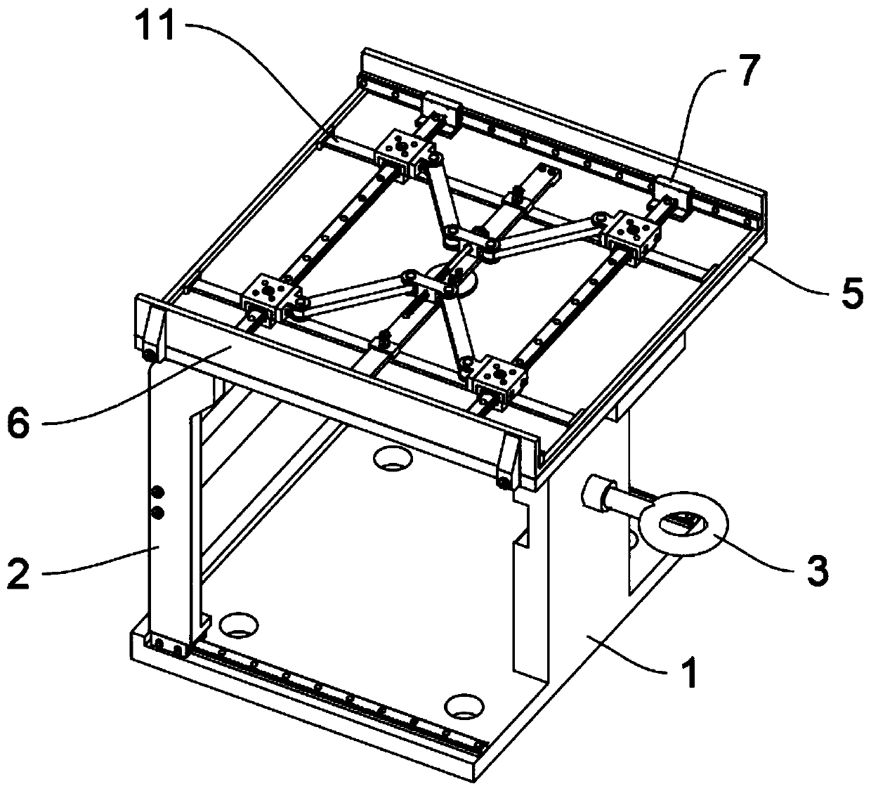
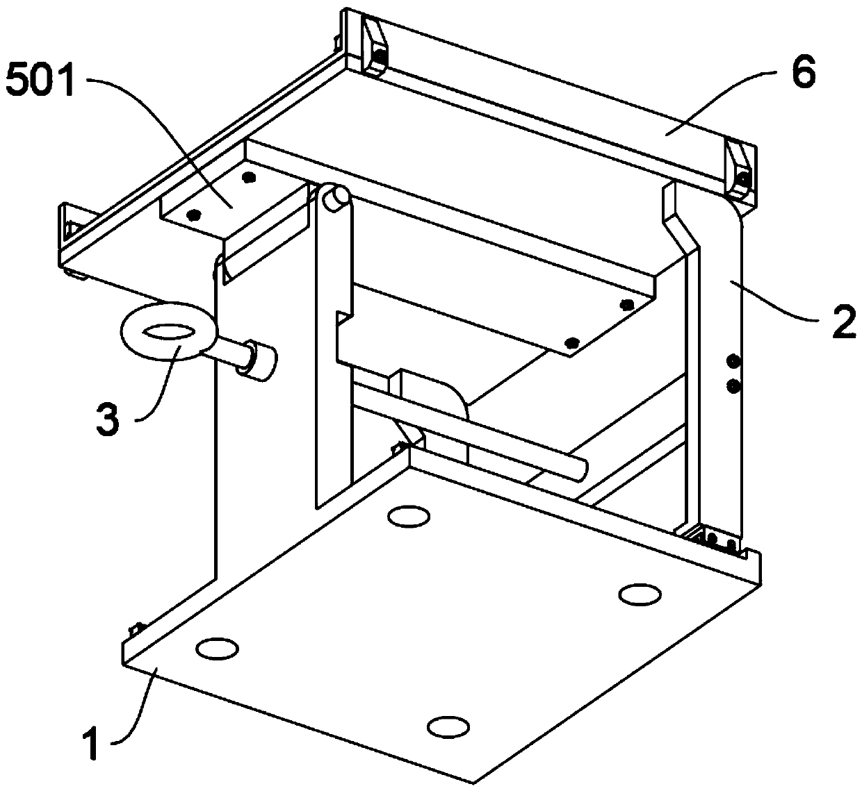
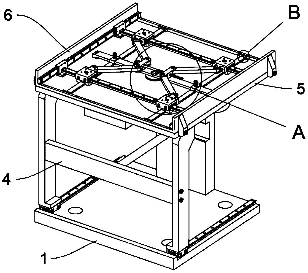
The invention provides a positioning mechanism for trial assembly for erection of a platform type power tower. The positioning mechanism includes a base, two sets of guide rails are fixedly arranged on both sides of the top of the base through bolts, and side supporting plates are fixedly arranged on the tops of guide rail sliding blocks of the base through bolts; a connection plate is fixedly connected between the two sets of the side supporting plates through bolts; four sets of through holes are formed in the bottom of the base; and a vertical plate structure is integrally arranged on one side of the base, a threaded barrel structure is integrally arranged in the middle of the vertical plate structure, a jacking screw is movably arranged in the middle of the vertical plate structure, and a circular structure is integrally arranged on the outer side of the jacking screw. By arranging the side supporting plates and the jacking screw, the function of 90-degree rotary installation is provided for the positioning mechanism, the power tower can be conveniently and horizontally subjected to trial assembly, other tests are conducted by rotating righting after assembly, the assembly structure is stable, rotation operation is easy, the circular structure is arranged on the outer side of the jacking screw, and auxiliary rotating is conveniently conducted by using a rod-shaped tool.

Description

technical field [0001] The invention relates to the technical field of power tower positioning, and more specifically relates to a positioning mechanism for trial assembly for erecting a platform-type power tower. Background technique [0002] The power tower is a trapezoidal or triangular tower-shaped building, usually 25-40 meters high, and is a steel frame structure. Electric towers are mostly built near power plants and distribution stations in the field. It is an important facility in the power sector, which can overhead wires and play a role in protection and support. The design, manufacture, installation, maintenance and quality inspection of power towers are important guarantees for the operation and development of modern power systems. [0003] Based on the above, the currently used trial assembly mechanism components mainly fix the tower through a fixed plate structure, and it is inconvenient to locate the power tower with errors in the manufacturing process, and ...

Claims


Application Information

Patent Timeline
Patent Type & Authority Applications(China)
IPC IPC(8): E04H12/22E04H12/34
CPCE04H12/2253E04H12/2284E04H12/34
Inventor 刘爽
Owner 刘 爽
Why Eureka
Try Eureka