
Door fitting and clothes treating apparatus

A technology for clothes processing equipment and doors, which is applied to washing devices, other washing machines, household clothes dryers, etc. It can solve the problems of misalignment between door hooks and other locking parts and equipment cabinets, difficulty in closing doors, and sagging, etc., to improve the use of Experience, reduce production costs, and simplify the effect of product structure

Active Publication Date: 2020-01-10
WUXI LITTLE SWAN ELECTRIC CO LTD
View PDF6 Cites 2 Cited by
  • Summary
  • Abstract
  • Description
  • Claims
  • Application Information

AI Technical Summary

Problems solved by technology

[0002] At present, the doors of drum washing machines and other equipment will sag after long-term use, resulting in misalignment between the locking parts such as door hooks and the cabinet of the equipment, making it difficult to close the door

Method used


Image

  • Door fitting and clothes treating apparatus
  • Door fitting and clothes treating apparatus
  • Door fitting and clothes treating apparatus

Examples


Embodiment 1

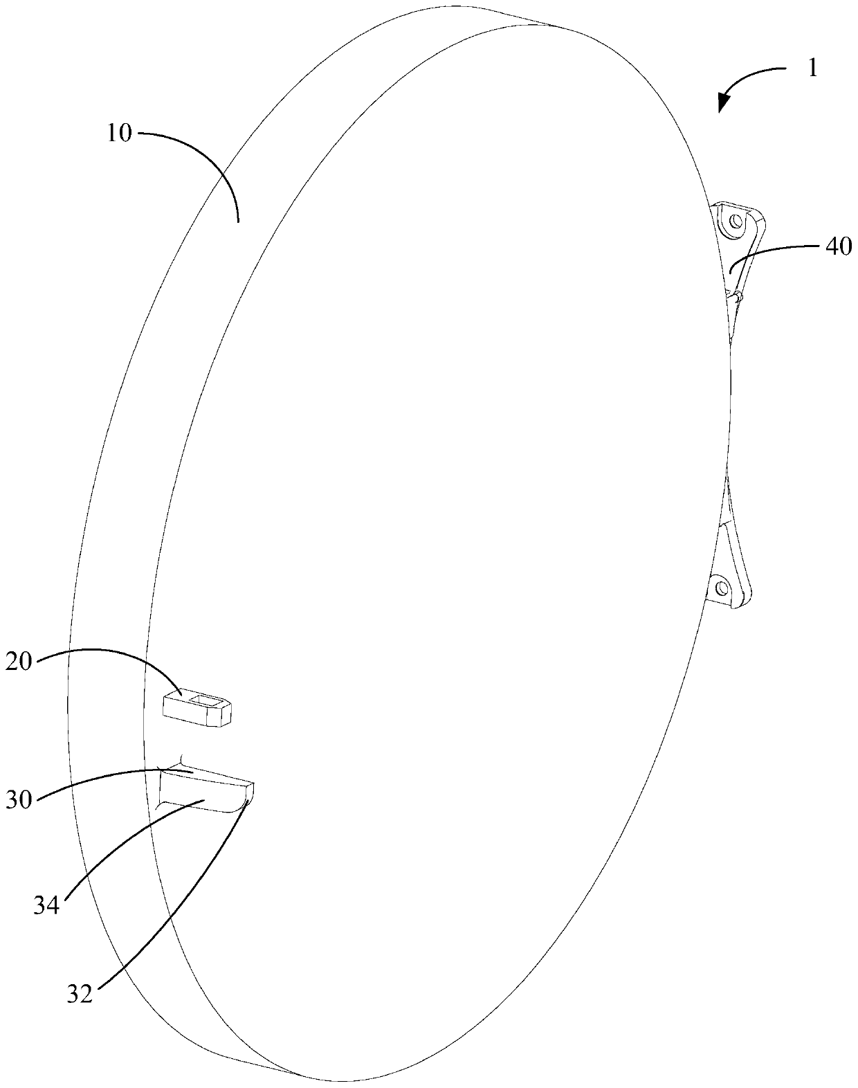
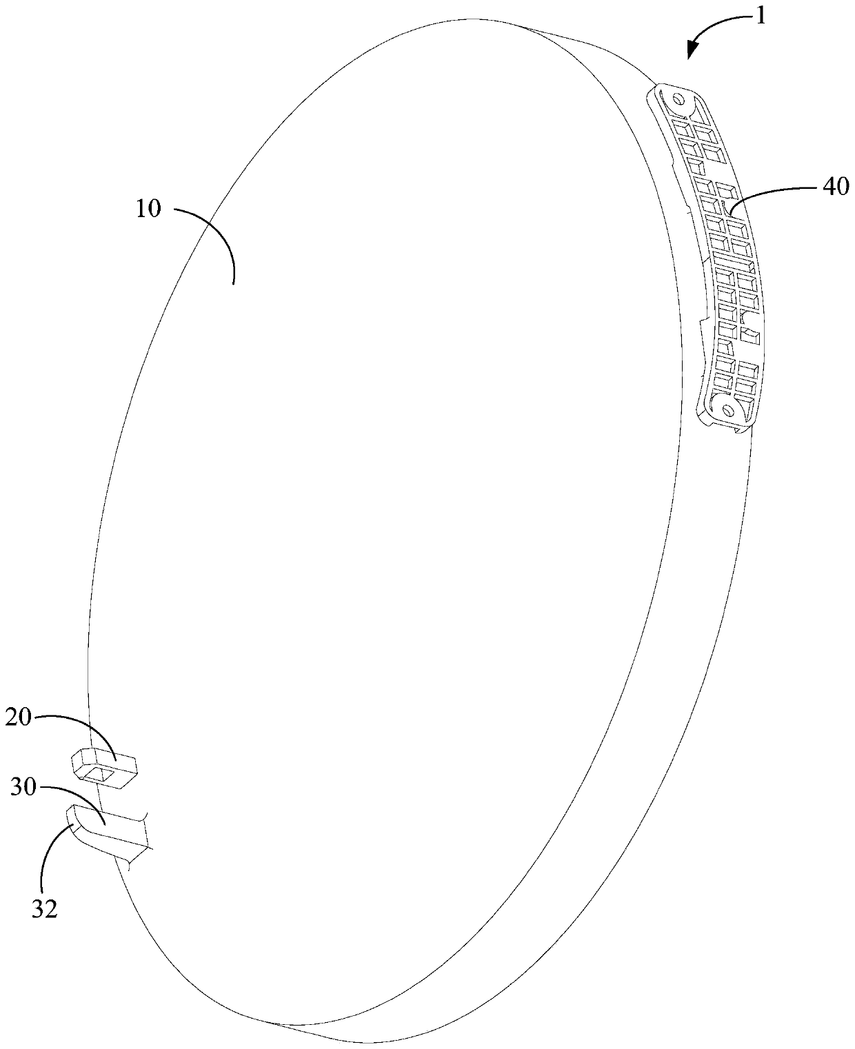
[0056] A door device 1 includes: a door body 10 and a positioning part 30 .

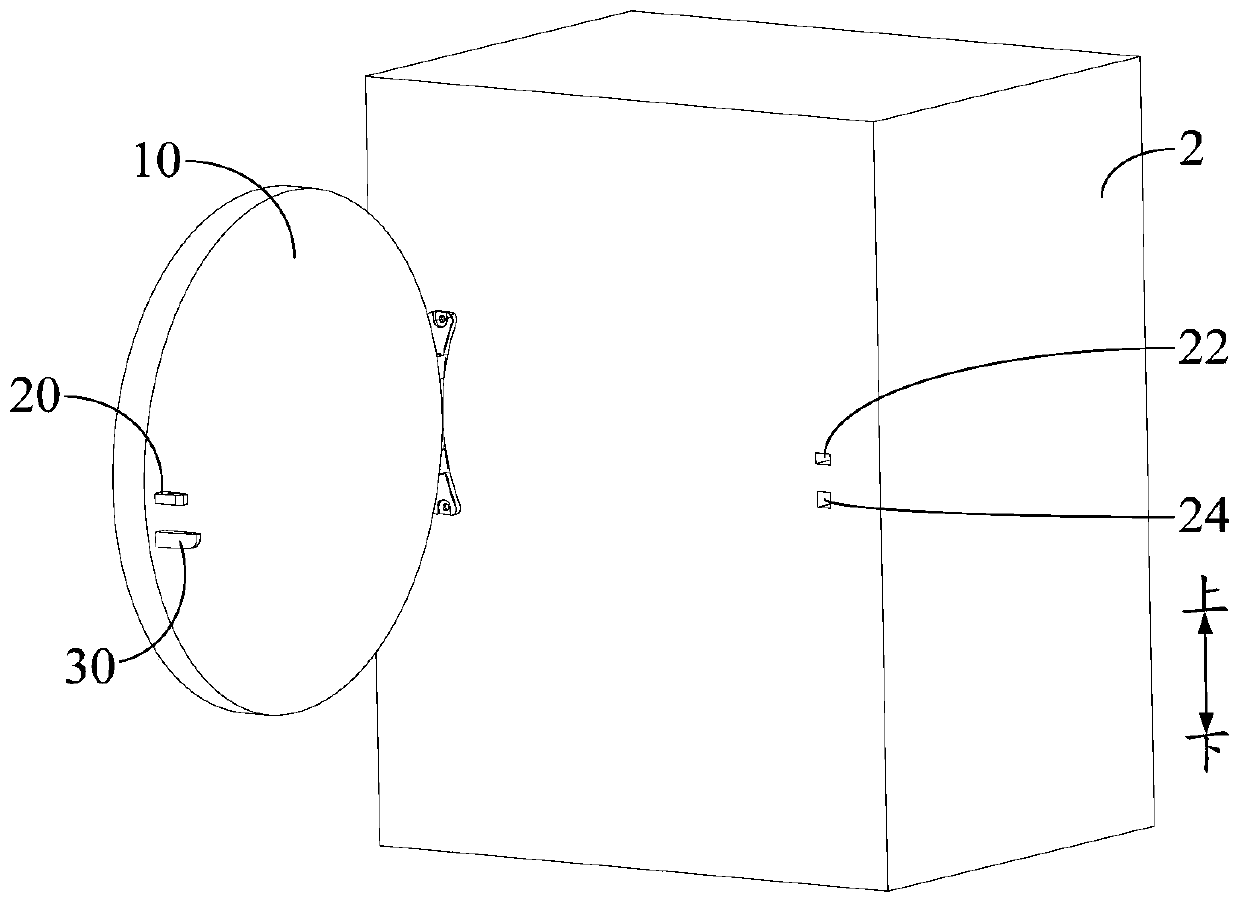
[0057] Specifically, the positioning part 30 is arranged on the door body 10, and the bottom of the end of the positioning part 30 away from the door body 10 is provided with a guide slope 32, such as figure 2 , image 3 shown. Wherein, the guide slope 32 extends obliquely upward along the direction away from the door body 10, as Figure 5 with Image 6 As shown, it is used to cooperate with the box body 2 to locate the relative position of the door unit 1 and the box body 2. The positioning part 30 can be a positioning post, a positioning bump, a positioning convex hull, etc., and can cooperate with a positioning hole, a supporting surface, etc. provided on the box body.

[0058] The door device 1 provided in this embodiment, by adding a positioning part 30 on the door body 10, utilizes the cooperation of the positioning part 30 and the box body 2 to locate the relative position of the door par...

Embodiment 2

[0069] The difference from the first embodiment is that the guide slope 32 is a plane.

[0070] The principle is basically the same as that of Embodiment 1, and will not be repeated here.

Embodiment 3

[0072] On the basis of any of the above embodiments, further, the length L1 between the end of the positioning part 30 away from the door body 10 and the door body 10 is greater than the distance L2 between the end of the locking part 20 away from the door body 10 and the door body 10 ,Such as Figure 5 As shown, the positioning part 30 starts to cooperate with the box body 2 before the locking part 20 when the door device 1 is closed.

[0073] When L1 is greater than L2, when the door device 1 sags, during the door closing process, the positioning part 30 first contacts the box body 2, and the position of the door part device 1 is raised by using the guide slope 32 to cooperate with the box body 2, so that the locking part 20 Accurate alignment with the box body 2, and then the locking part 20 can cooperate with the box body 2 to play the role of locking the door body 10 and the box body 2, which can effectively prevent the locking part 20 from interfering with the box body 2...


PUM


Abstract

The invention provides a door fitting and a clothes treating apparatus; the door fitting comprises: a door; and a positioning part, arranged on the door, wherein the bottom of one end, far away from the door, of the positioning part is provided with a guide inclined plane, and the guide inclined plane obliquely extends upwards along the direction far away from the door and is used for being matched with a box to fix the relative position of the door fitting and the box. The positioning part is additionally arranged on the door, the relative position of the door fitting and the box is positioned through the matching of the positioning part and the box, and therefore, the position accuracy of the door fitting and the box in the door closing process is guaranteed, the situation that the dooris difficult to close since a locking part and the box are staggered due to the drooping of the door fitting is prevented, and the user experience is improved.

Description

technical field [0001] The present invention relates to the technical field of clothes processing equipment, in particular, to a door device and a clothes processing device including the door device. Background technique [0002] At present, the doors of equipment such as drum washing machines will sag after long-term use, resulting in dislocation between locking parts such as door hooks and the cabinet of the equipment, making it difficult to close the door. Contents of the invention [0003] In order to solve at least one of the above technical problems, an object of the present invention is to provide a door device. [0004] Another object of the present invention is to provide a laundry treatment device comprising the above-mentioned door unit. [0005] In order to achieve the above object, the technical solution of the first aspect of the present invention provides a door device, including: a door body; A guide slope is provided, and the guide slope extends obliquel...

Claims


Application Information

Patent Timeline
IPC IPC(8): D06F39/14D06F58/20
CPCD06F39/14D06F58/20
Inventor 周震东苗雨来
Owner WUXI LITTLE SWAN ELECTRIC CO LTD
Learn More