Door panel spraying device

A technology of spraying device and door panel, which is applied in spraying device, painting room, etc., can solve the problems of low efficiency and long pause time, and achieve the effect of reducing impact, improving painting efficiency and reducing painting downtime.

Active Publication Date: 2021-07-13
重庆市佳禾家具制造有限公司
View PDF18 Cites 0 Cited by
  • Summary
  • Abstract
  • Description
  • Claims
  • Application Information

AI Technical Summary

Problems solved by technology

[0003] The purpose of the present invention is to provide a door panel spraying device to solve the problem of low efficiency caused by the long pause time of the door panel painting in the prior art

Method used


Image

  • Door panel spraying device
  • Door panel spraying device
  • Door panel spraying device

Examples


Embodiment 1

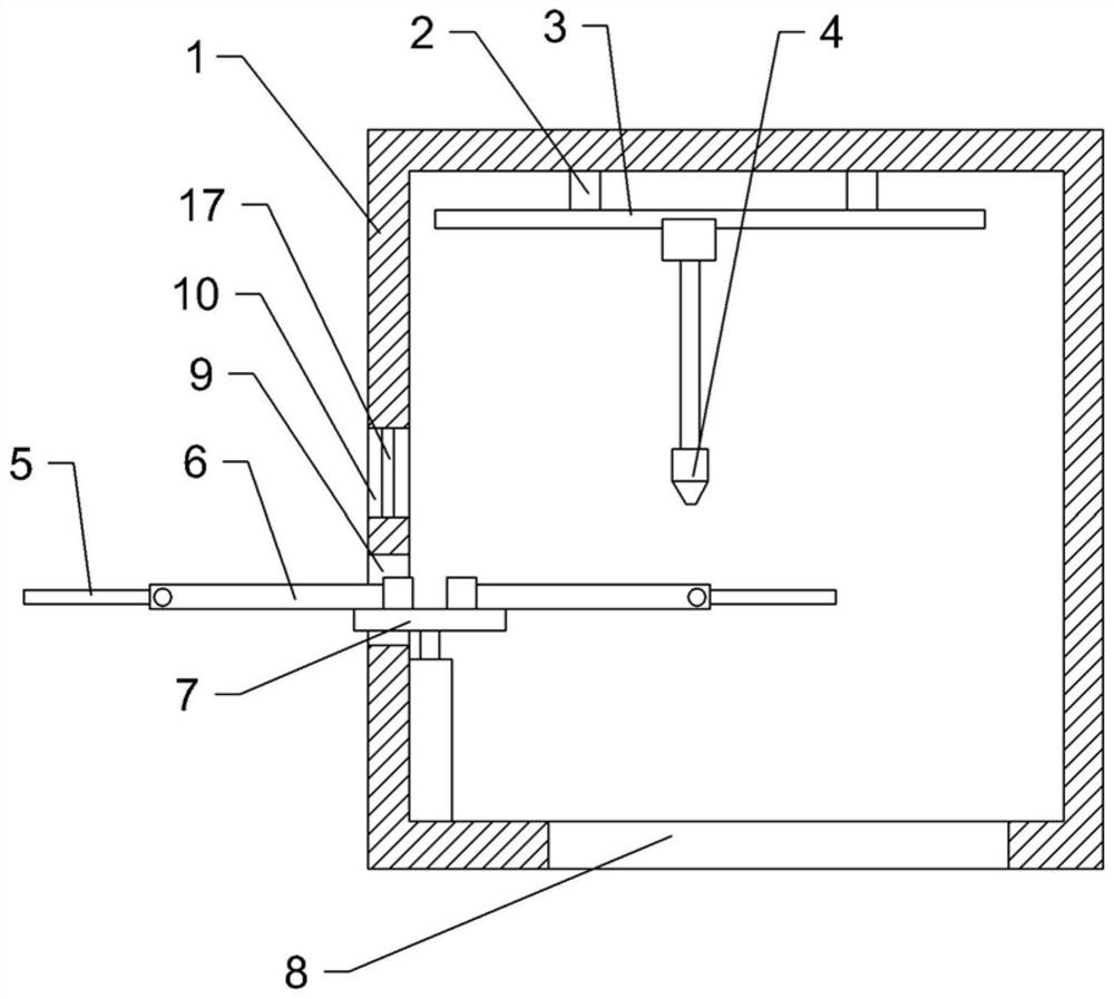
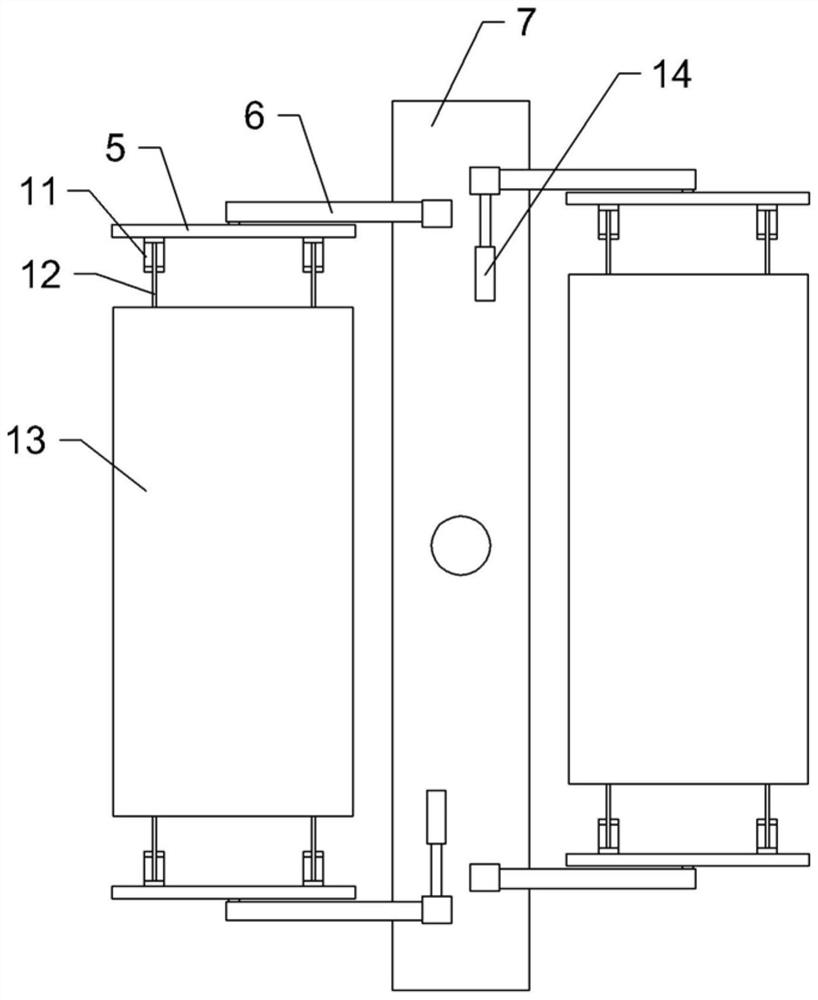
[0021] Embodiment one: as attached figure 1 and figure 2 Shown: a door panel spraying device, including a cuboid box 1, the side of the box 1 is provided with a pick-and-place opening 9, and an observation window 10 is opened on the upper side of the pick-and-release opening 9, and a transparent The observation plate 17, the bottom of the box body 1 has an exhaust port 8; the top inside the box body 1 is connected with the first guide rail 2 by bolts, and the first guide rail 2 is parallel to the length direction of the box body 1; on the first guide rail 2 The first rack is bolt-connected along the length direction; the first slider is slidably connected to the first guide rail 2, the first slider is connected with the first servo motor by bolts, and the key on the first servo motor is connected with the first tooth rack. The first gear meshed with the bar; the second guide rail 3 is slidably connected to the first slider along the width direction parallel to the box body 1...

Embodiment 2

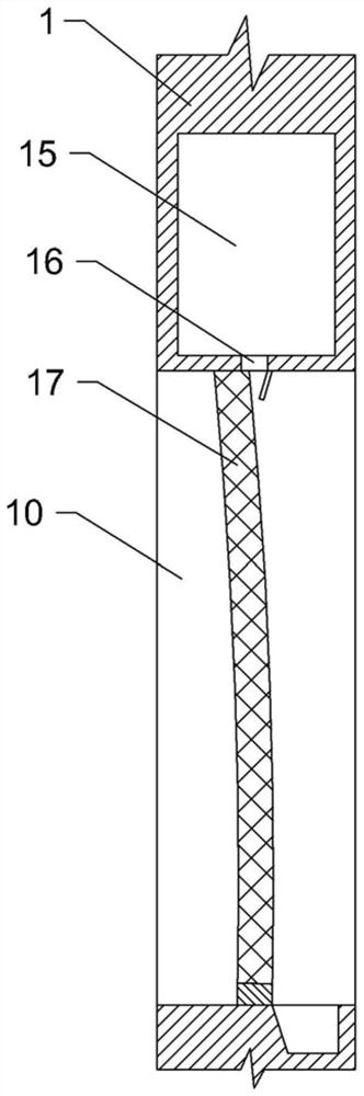
[0025] Embodiment 2: The difference from Embodiment 1 is only that a water curtain mechanism is provided on the side opposite to the pick-and-place opening 9 inside the box body 1, and the water curtain mechanism includes a water spray pipe connected to the top of the box body 1 and a water curtain mechanism. The sump located at the bottom of the box body 1, the water spray pipe is connected to the water pump, and the water pump sprays water from the water spray pipe and flows into the sump to form a water curtain; image 3As shown, on the casing 1, a water storage chamber 15 is provided on the upper side of the observation window 10, and the bottom of the water storage chamber 15 is provided with a drainage hole 16 communicating with the observation window 10; Through the flexible connection of the rubber block, the upper end of the observation plate 17 is integrally formed with a stopper, and the stopper slides and covers the lower side of the drain hole 16, and the side of t...


PUM


Abstract

The invention belongs to the technical field of plate spraying equipment, and is specifically a door panel spraying device, which includes a box body, the side of the box body is provided with a pick-and-place opening, the top inside the box body is provided with a movable spray head, and a support platform is provided below the spray head , the support platform is rotationally connected with the bottom of the box body, two support mechanisms are arranged laterally on the support platform, and the two support mechanisms are respectively located on both sides of the rotation axis of the support platform, and the two support mechanisms play a role in the rotation of the support platform. The bottom can be alternately located on both sides of the pick-and-place opening; the support mechanism includes two relatively movable upper and unloading mechanisms, the upper unloading mechanism includes an overturning component and a supporting component, and the overturning component is connected to the support platform through the supporting component; The bottom of the box is provided with an exhaust port. This solution solves the problem of low efficiency caused by long pause time when spraying paint on the door panel in the prior art.

Description

technical field [0001] The invention belongs to the technical field of plate spraying equipment, in particular to a door panel spraying device. Background technique [0002] In the operation of painting the surface of the door panel, spraying is a relatively common method. Existing spraying generally all is to spray paint to the surface of door panel by high-pressure gas. In order to reduce the labor intensity of workers, by setting a box with an opening, the door panel is placed in the box for spraying operation, which can reduce the labor intensity of workers, and also keep workers away from the paint mist generated during spraying, which is beneficial to workers. In good health. However, manual handling is still required when the door panel enters and exits the box body, which will reduce the continuity of the spraying operation, thereby affecting the production efficiency of spraying. Contents of the invention [0003] The object of the present invention is to provi...

Claims


Application Information

Patent Timeline
Patent Type & Authority Patents(China)
IPC IPC(8): B05B13/02B05B14/40B05B15/55B05B16/40
CPCB05B13/0221B05B13/0271B05B14/40B05B15/55B05B16/40
Inventor 唐静
Owner 重庆市佳禾家具制造有限公司
Why Eureka
Try Eureka