Pedal device and vehicle
A pedal and driving device technology, applied in the field of vehicles, can solve the problems of poor comfort, increased vehicle body width, and limited extension, so as to reduce the possibility of failure, increase the extension, and improve comfort sexual effect
- Summary
- Abstract
- Description
- Claims
- Application Information
AI Technical Summary
Problems solved by technology
Method used
Image
Examples
Embodiment 1
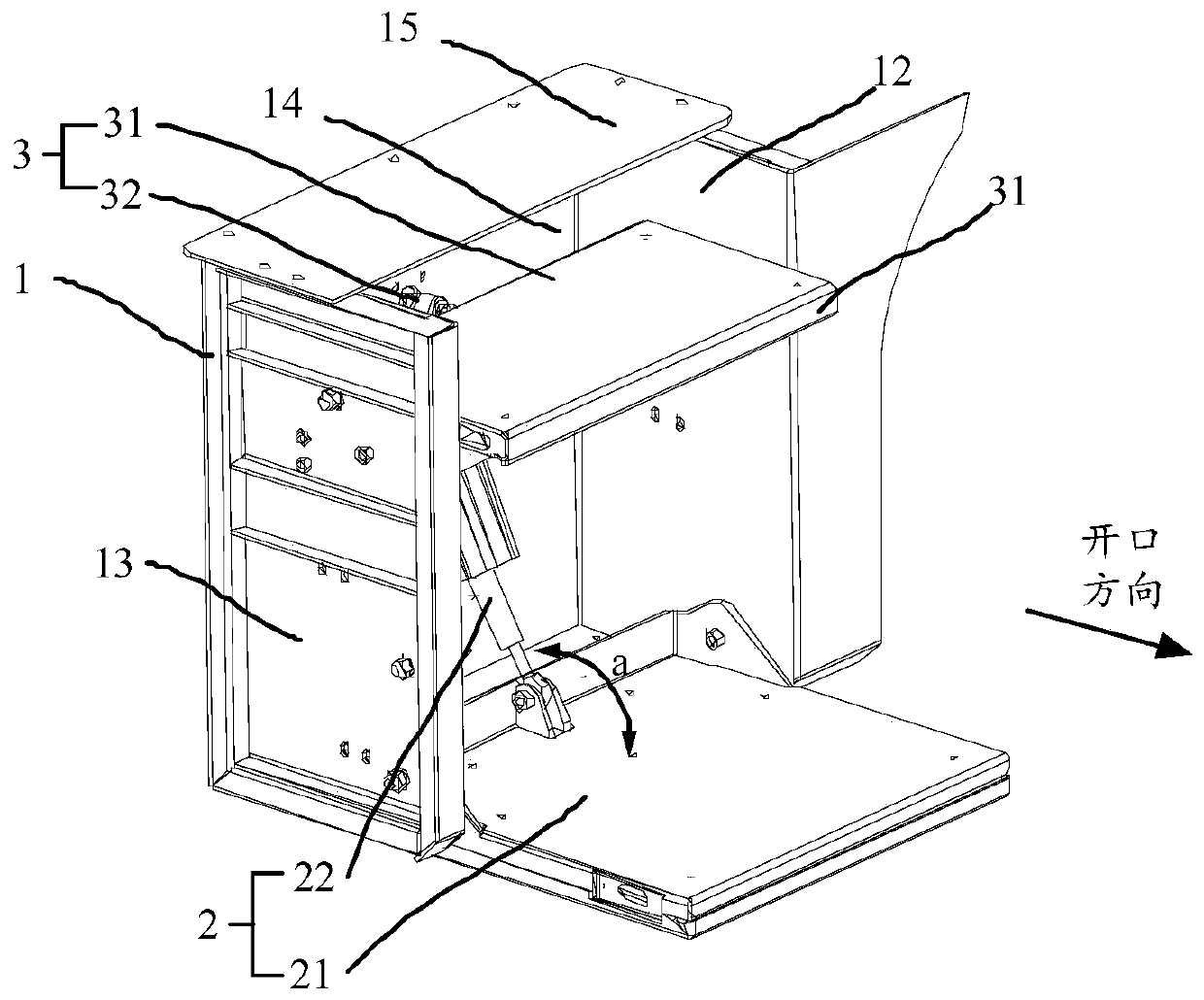
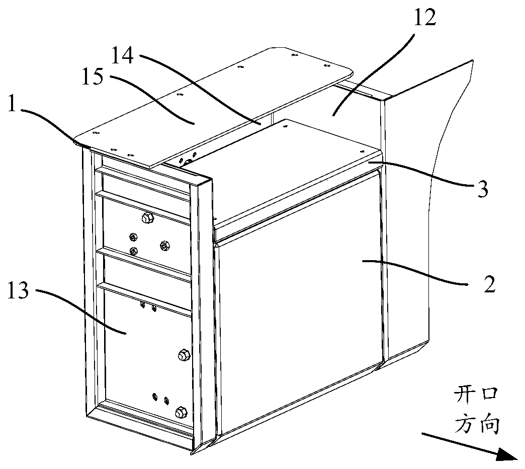
[0045] A pedal device is provided in this embodiment, such as figure 1 As shown, it includes a frame structure 1 , a first pedal assembly 2 and a second pedal assembly 3 . The frame structure 1 is a cuboid structure with an opening on one side as a whole, including a left side wall 12 and a right side wall 13 on both sides of the opening, a rear side wall 14 opposite to the opening, and a connecting plate 15 on the top. The first pedal assembly 2 and the second pedal assembly 3 are disposed between the left side wall 12 and the right side wall 13 . Specifically, the first pedal assembly 2 includes a first pedal 21 and a self-locking cylinder 22 connected to the first pedal 21, the first pedal 21 is rotatably connected to the left side wall panel 12 and the right side wall panel 13, and the self-locking cylinder The cylinder barrel of 22 is rotatably connected with the rear side wall plate 14, and the piston rod of the self-locking cylinder 22 is rotatably connected with the e...
Embodiment 2
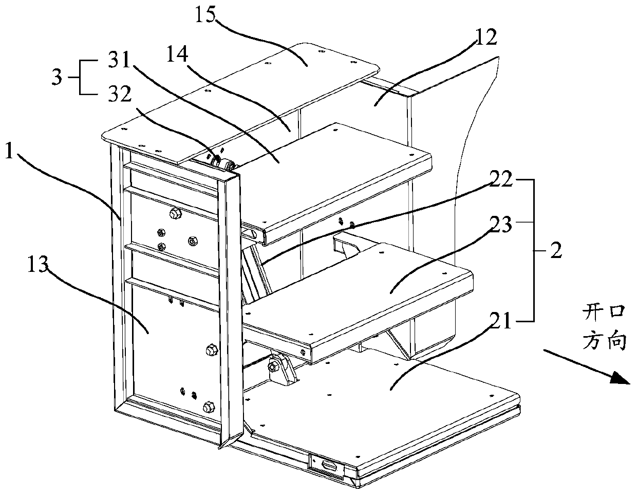
[0047] A pedal device is provided in this embodiment, such as image 3 As shown, it includes a frame structure 1 , a first pedal assembly 2 and a second pedal assembly 3 . The frame structure 1 is a cuboid structure with an opening on one side as a whole, including a left side wall 12 and a right side wall 13 on both sides of the opening, a rear side wall 14 opposite to the opening, and a connecting plate 15 on the top. The first pedal assembly 2 and the second pedal assembly 3 are disposed between the left side wall 12 and the right side wall 13 .
[0048] Specifically, such as Figure 4 As shown, the first pedal assembly 2 includes a first pedal 21, a third pedal 23, a connecting rod 24 and a self-locking cylinder 22, and the first pedal 21 and the third pedal 23 are connected to the left side wall plate 12 and the right side wall plate 13 respectively. Rotatably connected, the rotation axis of the third pedal 23 is positioned above the rotation axis of the first pedal 21;...
Embodiment 3
[0052] This embodiment provides a pedal device, which is further improved on the basis of the second embodiment. Such as Figure 6 As shown, the second pedal assembly 3 also includes two limit pin shafts 33, which are arranged between the left side wall plate 12 and the right side wall plate 13 of the frame structure 1, and the two ends of each limit pin shaft 33 are respectively It is fixedly connected with the left side wall plate 12 and the right side wall plate 13, and two limit pin shafts 33 are arranged at intervals along the horizontal direction. The second pedal 31 is provided with a limit hole 311 corresponding to the limit pin shaft 33. The pedal 31 is sheathed on the limiting pin shaft 33 through the limiting hole 311 . Wherein, the cross-section of the limiting hole 311 is a bar-shaped structure, and the long side of the bar-shaped structure extends along the horizontal direction, so that when the telescopic cylinder 32 drives the second pedal 31 to slide, the sho...
PUM
 Abstract
Description
Claims
Application Information
 - R&D
- Intellectual Property
- Life Sciences
- Materials
- Tech Scout
- Unparalleled Data Quality
- Higher Quality Content
- 60% Fewer Hallucinations
Browse by: Latest US Patents, China's latest patents, Technical Efficacy Thesaurus, Application Domain, Technology Topic, Popular Technical Reports.
© 2025 PatSnap. All rights reserved.Legal|Privacy policy|Modern Slavery Act Transparency Statement|Sitemap|About US| Contact US: help@patsnap.com


