
Vehicle-mounted GNSS (Global Navigation Satellite System) signal compensation device and positioning system and method

A signal compensation and positioning system technology, which is applied in satellite radio beacon positioning systems, measurement devices, radio wave measurement systems, etc., can solve problems such as reducing user experience and increasing operating costs of self-built positioning systems, so as to improve user experience, Effects that are easy to scale

Pending Publication Date: 2019-12-31
KUNCHEN TECH CO LTD
View PDF4 Cites 0 Cited by
  • Summary
  • Abstract
  • Description
  • Claims
  • Application Information

AI Technical Summary

Problems solved by technology

When using the above-mentioned self-built positioning system for positioning and navigation, since the existing vehicle navigation or mobile phones and other terminals do not integrate positioning modules that can adapt to all signal systems, the user needs to be equipped with additional equipment that is compatible with the specific signal system in the positioning system. Matching positioning terminal equipment, for example, users need to distribute corresponding positioning terminal equipment when they enter the coverage area of ​​self-built positioning system, and then return the corresponding equipment when they leave. additional operating costs

Method used


Image

  • Vehicle-mounted GNSS (Global Navigation Satellite System) signal compensation device and positioning system and method
  • Vehicle-mounted GNSS (Global Navigation Satellite System) signal compensation device and positioning system and method
  • Vehicle-mounted GNSS (Global Navigation Satellite System) signal compensation device and positioning system and method

Examples


Embodiment Construction

[0012] Specific embodiments of the present invention will be described in detail below, and it should be noted that the embodiments described here are only for illustration, not for limiting the present invention. In the following description, numerous specific details are set forth in order to provide a thorough understanding of the present invention. It will be apparent, however, to one of ordinary skill in the art that these specific details need not be employed to practice the present invention. In other instances, well-known circuits, materials or methods have not been described in detail in order to avoid obscuring the present invention.

[0013] Throughout this specification, reference to "one embodiment," "an embodiment," "an example," or "example" means that a particular feature, structure, or characteristic described in connection with the embodiment or example is included in the present invention. In at least one embodiment. Thus, appearances of the phrases "in on...


PUM


Abstract

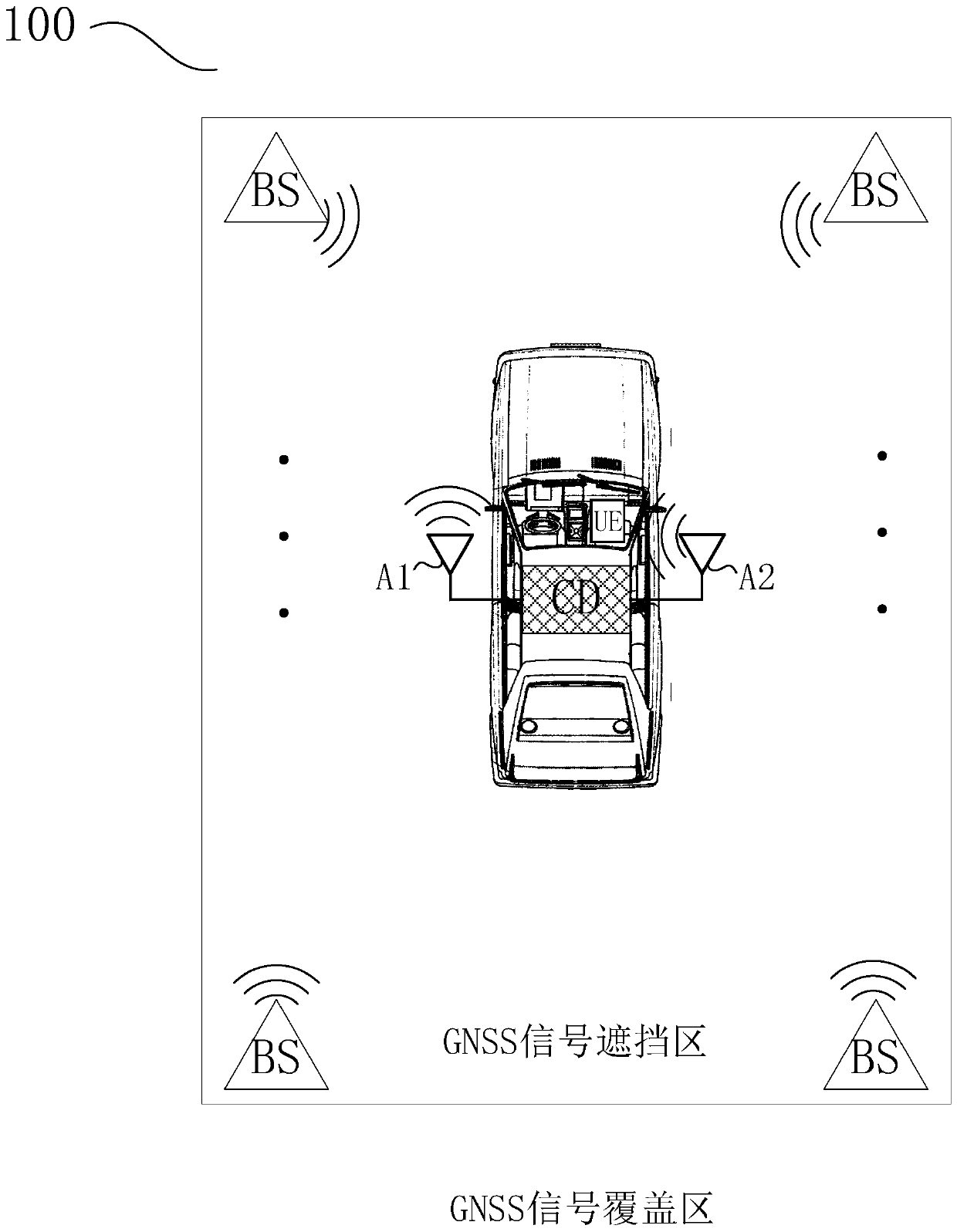
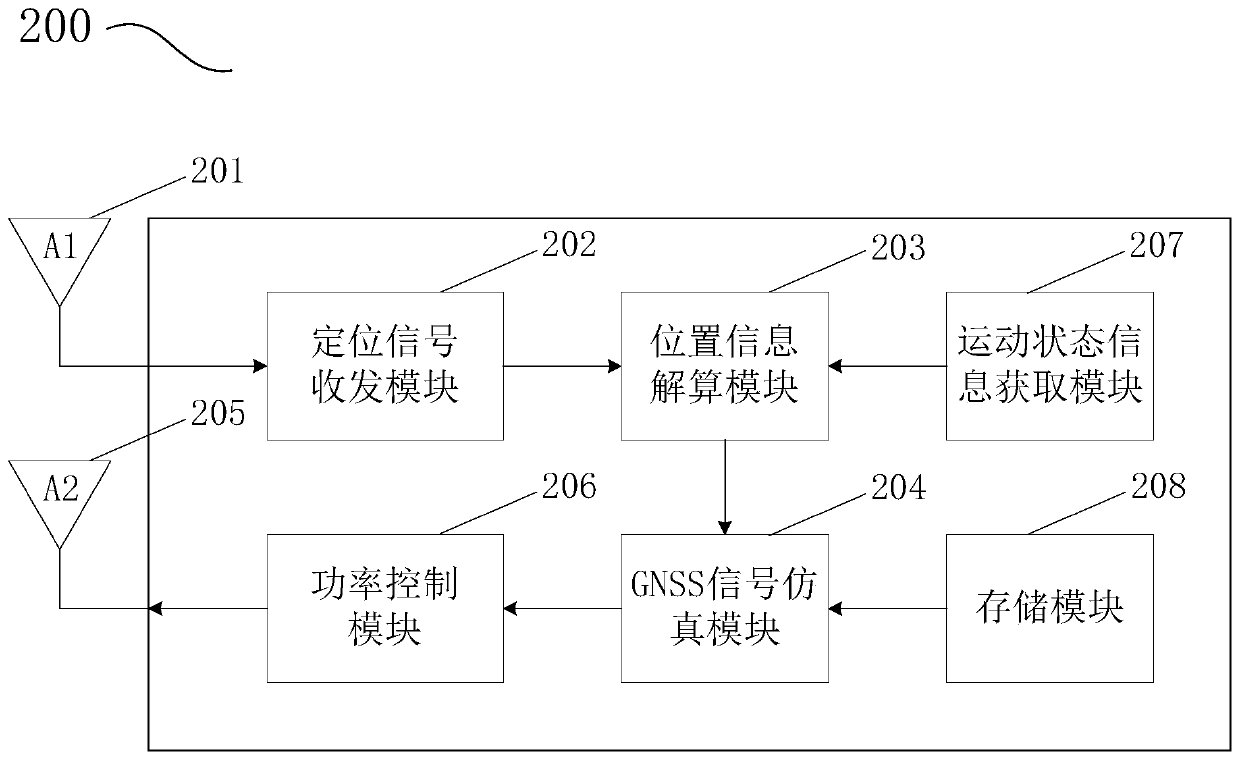
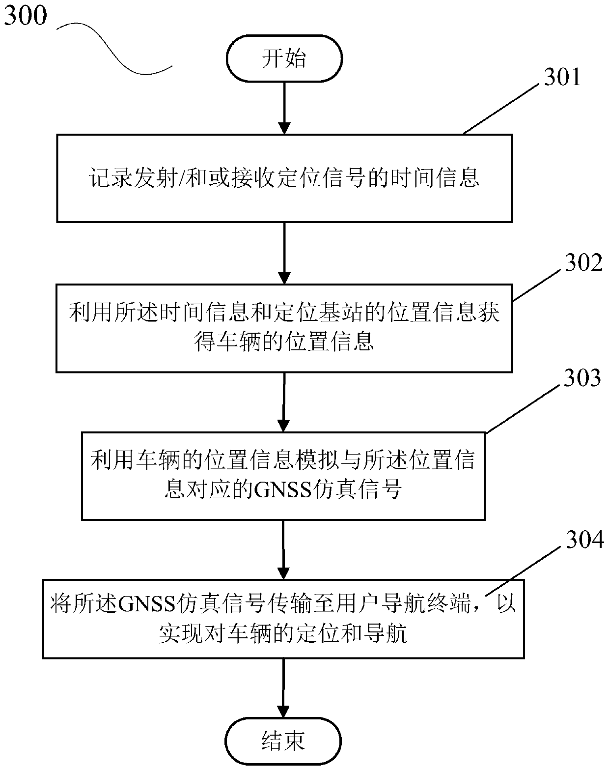
The invention discloses a vehicle-mounted GNSS (Global Navigation Satellite System) signal compensation device and a vehicle-mounted GNSS signal blind compensation positioning system and method. The vehicle-mounted GNSS signal compensation device comprises a first antenna, a positioning signal receiving and transmitting module, a position information resolving module, a GNSS signal simulation module and a second antenna, wherein the first antenna receives a positioning signal from a positioning base station; the positioning signal transceiving module receives the positioning signal from the positioning base station from the first antenna and / or generates a positioning signal to transmit the positioning signal to the positioning base station through the first antenna, and records time information of transmitting and / or receiving the positioning signal; the position information resolving module receives the time information to resolve position information of a vehicle; the GNSS signal simulation module acquires the position information of the vehicle to simulate a corresponding GNSS simulation signal; and the second antenna receives the GNSS simulation signal and radiates the GNSS simulation signal to a navigation terminal inside the vehicle. The technical scheme of the invention realizes seamless connection of GNSS positioning, is easy to popularize, can be compatible with the existing vehicle-mounted navigation and mobile phone navigation, and improves the user experience.

Description

technical field [0001] The invention relates to the field of wireless communication, in particular to a vehicle-mounted GNSS signal blind complement positioning device, system and method. Background technique [0002] With the rapid development of urban construction, the continuous improvement of people's living standards, and the increasing number of private vehicles, the scene of driving vehicles to unfamiliar roads and areas in the city is becoming more and more common, which has led to people using navigation equipment for vehicle navigation. The frequency is increasing day by day. Existing navigation equipment, whether it is a vehicle navigation equipment or a terminal navigation equipment such as a mobile phone, is based on GNSS (Global Navigation Satellite System) satellite signals to achieve positioning, for example, GPS satellite signals in the United States, GLONASS satellite signals in Russia, GALILEO satellite signals in the EU and China's Beidou satellite signa...

Claims


Application Information

Patent Timeline
IPC IPC(8): G01S19/45G01S19/37
CPCG01S19/45G01S19/37Y02D30/70
Inventor 袁韬韬黄伟朱晓章
Owner KUNCHEN TECH CO LTD
Learn More