
Fuel cell hydrogen test system and test method

A fuel cell and test system technology, applied in the direction of fuel cells, fuel cell control, fuel cell additives, etc., can solve the problems of low analysis efficiency and reliability

Active Publication Date: 2019-12-27
SHANGHAI ELECTRICGROUP CORP
View PDF5 Cites 17 Cited by
  • Summary
  • Abstract
  • Description
  • Claims
  • Application Information

AI Technical Summary

Problems solved by technology

[0004] The technical problem to be solved by the present invention is to provide a fuel cell hydrogen test system and test method in order to overcome the defects of low analysis efficiency and reliability in the functional analysis of the fuel cell hydrogen subsystem in the prior art

Method used


Image

  • Fuel cell hydrogen test system and test method
  • Fuel cell hydrogen test system and test method
  • Fuel cell hydrogen test system and test method

Examples


Embodiment 1

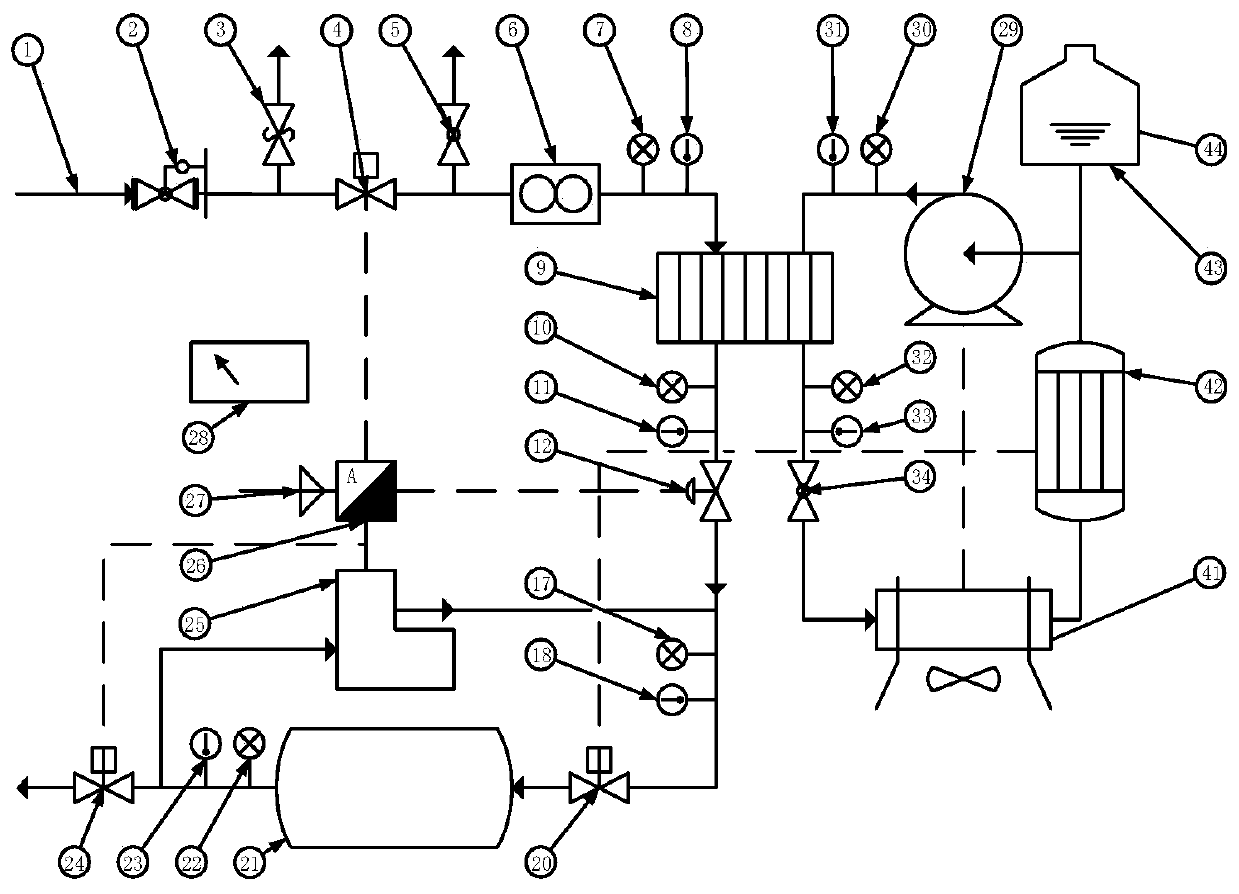
[0108] This implementation discloses a fuel cell hydrogen test system, such as figure 1 As shown, the fuel cell hydrogen test system includes: a heat exchanger 9 , a stack simulator 21 , a water supply module, a hydrogen supply module and a hydrogen circulation pump 25 . Wherein, the heat exchanger 9 has a first hydrogen flow channel and a first water flow channel, and the stack simulator 21 is used to simulate the stack under the working condition to be tested. The water supply module comprises a heating water tank 42, a booster pump 29 and a radiator 41, and the booster pump 29 is connected between the outlet of the heating water tank 42 and the inlet of the first water flow passage through a pipeline, so that the heated water in the heating water tank 42 The water 44 sucked out and pressurized is sent to the inlet of the first water channel, and the outlet of the first water channel is connected to the inlet of the heating water tank 42 through a pipeline. The hydrogen sup...

Embodiment 2

[0133] The structure of the fuel cell hydrogen test system in this embodiment is basically the same as that of the fuel cell hydrogen test system in Example 1. Simulation of the humidification function. Wherein, the same reference numerals in this embodiment and the first embodiment refer to the same elements.

[0134] like image 3 As shown, the fuel cell hydrogen test system further includes a humidifier 16 , and the humidifier 16 is located between the proportional valve 12 and the stack simulator 21 , and between the heat exchanger 9 and the heating water tank 42 . Wherein, the humidifier 16 has a second hydrogen flow channel and a second water flow channel, and the humidifier 16 is used for unidirectionally permeating the water passing through the second water flow channel to the second hydrogen flow channel. A water flow meter 39 is provided between the outlet of the second water channel and the heating water tank 42 . The hydrogen circulation pump 25 is connected bet...


PUM


Abstract

The invention discloses a fuel cell hydrogen test system and test method. The test system comprises a heat exchanger having a first hydrogen flow channel and a first water flow channel, a stack simulator, a water supply module comprising a heating water tank, a booster pump and a radiator, a hydrogen supply module and a hydrogen circulating pump, wherein the booster pump is connected between an outlet of the heating water tank and an inlet of the first water flow channel, the hydrogen supply module is connected with an inlet of the first hydrogen flow channel through a pipeline, an outlet of the first hydrogen flow channel is connected with an inlet of a galvanic pile simulator through a pipeline, a proportional valve is arranged between an outlet of the first hydrogen flow channel and theinlet of the galvanic pile simulator, the hydrogen circulating pump is connected between an outlet of the galvanic pile simulator and the outlet of the first hydrogen flow channel, temperature sensors and pressure sensors are arranged on a circulation path of hydrogen and a circulation path of the water, and a hydrogen flow meter is arranged between the hydrogen supply module and the inlet of thefirst hydrogen flow channel. The test system is advantaged in that efficiency and reliability of functional analysis of a fuel cell hydrogen subsystem are improved.

Description

technical field [0001] The invention relates to the field of performance testing of vehicle components, in particular to a fuel cell hydrogen testing system and testing method. Background technique [0002] With the update and application of fuel cell technology, the function and structure of the fuel cell hydrogen subsystem will also change in order to adapt to the new fuel cell technology. In order to understand the changes in its functions, it is necessary to develop a fuel cell hydrogen test system to analyze the functions of the fuel cell hydrogen subsystem in more detail and further improve the design of its structure. [0003] In the prior art, the hydrogen subsystem of the fuel cell is analyzed by analyzing the functions of each component (including flow, pressure, humidification function, heat dissipation function, heat exchange function and hydrogen circulation function), or simply connecting them, through The operation and debugging of its own components, analysi...

Claims


Application Information

Patent Timeline
IPC IPC(8): H01M8/04029H01M8/04089H01M8/04298H01M8/0432H01M8/0438
CPCH01M8/04305H01M8/04328H01M8/04388H01M8/04029H01M8/04097Y02E60/50
Inventor 熊宇林业发季文娇钱超
Owner SHANGHAI ELECTRICGROUP CORP
Learn More