Wide-angle lens and imaging equipment
A wide-angle lens and imaging surface technology, applied in optical components, optics, instruments, etc., can solve the problems of difficult to correct edge aberration, large incident angle of light, large f-θ distortion, etc., to eliminate chromatic aberration, large field of view, Effects of low tolerance sensitivity
- Summary
- Abstract
- Description
- Claims
- Application Information
AI Technical Summary
Problems solved by technology
Method used
Image

Examples
no. 1 example
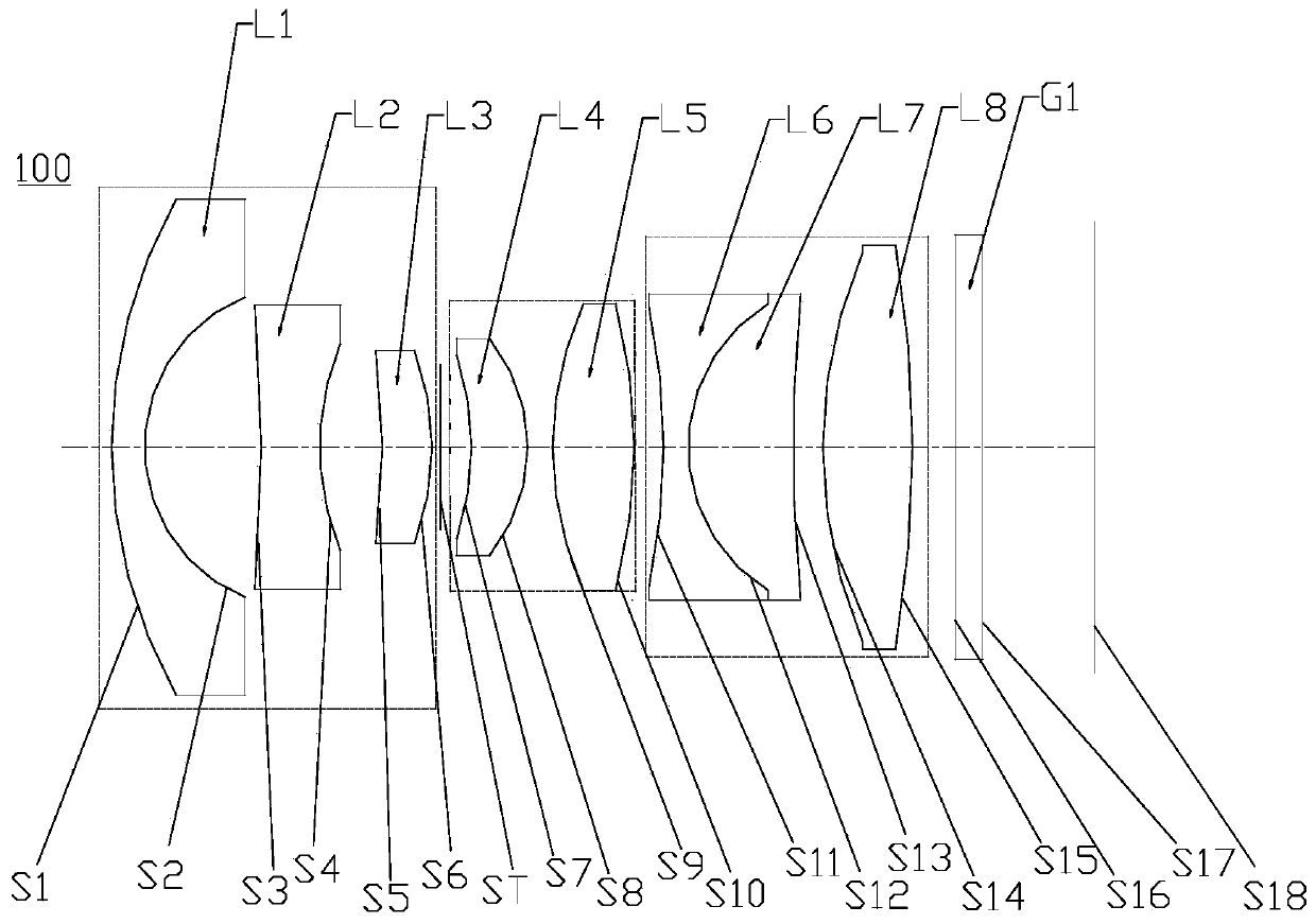
[0070] refer to figure 1 The wide-angle lens 100 provided by the first embodiment of the present invention includes in order from the object side to the imaging surface S18: a first group Q1, a stop ST, a second group Q2, a third group Q3, and a filter G1.
[0071] The first group Q1 has a negative power, and the first group Q1 sequentially includes two first lenses L1 with negative power, a second lens L2 with negative power, and a third lens with positive power L3, wherein the object-side surface S1 of the first lens L1 is convex, and the image-side surface S2 of the first lens L1 is concave, the object-side surface S3 of the second lens L2 is concave, and the image-side surface S4 of the second lens L2 is convex, the object-side surface S5 of the third lens L3 is concave, and the image-side surface S6 of the third lens L3 is convex.
[0072] The second group Q2 has positive refractive power, and the second group Q2 sequentially includes two fourth lenses L4 with positive r...
no. 2 example
[0085] For a structural schematic diagram of a wide-angle lens 200 provided in this embodiment, please refer to Image 6 . The wide-angle lens 200 in this embodiment is roughly the same as the wide-angle lens 100 in the first embodiment, except that the paraxial position of the image-side surface S11 of the second lens L2 of the first group Q1 of the wide-angle lens 200 in this embodiment is The fifth lens L5 of the second group Q2 is a glass spherical lens, the image-side surface S13 of the seventh lens L7 of the third group Q3 is a convex surface, and the curvature radius and material selection of each lens are different.
[0086] See Table 3 for lens-related parameters of each lens in the wide-angle lens 200 provided in this embodiment.
[0087] table 3
[0088]
[0089]
[0090] The parameters of each lens aspheric surface in this embodiment are shown in Table 4.
[0091] Table 4
[0092]
[0093] In this embodiment, its field curvature, distortion, axial chro...
no. 3 example
[0095] For a structural schematic diagram of a wide-angle lens 300 provided in this embodiment, please refer to Figure 11 . The wide-angle lens 300 in this embodiment is roughly the same as the wide-angle lens 100 in the first embodiment, the difference is that: the object-side surface S3 of the second lens L2 of the first group Q1 of the wide-angle lens 300 in this embodiment is a convex surface, The object-side surface S5 of the third lens L3 is convex, and the image-side surface S6 of the third lens L3 is concave, the third lens L3 has negative refractive power, and the object-side surface S7 of the fourth lens L4 of the second group Q2 is a concave surface, the fifth lens L5 is a glass spherical lens, and the object-side surface S9 of the fifth lens L5 is a concave surface, the sixth lens L6 of the third group Q3 has positive refractive power, and the object-side surface S11 of the sixth lens L6 and the image-side surface S12-1 of the sixth lens L6 are convex, the sevent...
PUM
 Abstract
Description
Claims
Application Information
 - R&D
- Intellectual Property
- Life Sciences
- Materials
- Tech Scout
- Unparalleled Data Quality
- Higher Quality Content
- 60% Fewer Hallucinations
Browse by: Latest US Patents, China's latest patents, Technical Efficacy Thesaurus, Application Domain, Technology Topic, Popular Technical Reports.
© 2025 PatSnap. All rights reserved.Legal|Privacy policy|Modern Slavery Act Transparency Statement|Sitemap|About US| Contact US: help@patsnap.com