
Site groundwater pollutant automatic tracing method

A technology for pollutants and groundwater, applied in the fields of surface/boundary effects, instruments, electrical and digital data processing, etc., which can solve the problems of large calculation amount of traceability models, high professional quality requirements, and limited promotion, and achieve the effect of weakening adverse effects.

Active Publication Date: 2019-12-20
SICHUAN INST OF GEOLOGICAL ENG INVESTIGATION
View PDF15 Cites 4 Cited by
  • Summary
  • Abstract
  • Description
  • Claims
  • Application Information

AI Technical Summary

Benefits of technology

This patented technology helps detect contaments at different locations within an underground water body through measuring their levels overcomes previous methods requiring manual labor or expensive equipment. It also allows for automated tracking across areas without human error during operation. By analyzing these measurements from various sources like soil samples taken from each section, polluted sites are identified early and appropriate actions (such as reducing chemicals) could be initiated earlier before they become problematic.

Problems solved by technology

This patented technical problem addressed in this patents relates to finding accurate locations of contaminated sites during remediation efforts due to rapid changes caused by water pollution from surface runoff. Current techniques have difficulty accurately identifying where polluted areas may exist but require expensive equipment that only works at specific times. Therefore there needs an improved technique called tracerless soil science that allows for more precise locating of polluting materials without requiring costly infrastructure modifications.

Method used


Image

  • Site groundwater pollutant automatic tracing method
  • Site groundwater pollutant automatic tracing method
  • Site groundwater pollutant automatic tracing method

Examples


Embodiment 1

[0048] A method for automatic traceability of groundwater pollutants on site, comprising the following steps:

[0049] Step 1. Obtain the shortest time for pollutants from the main test hole to the observation holes in the main direction and the longest time for pollutants to go from the main test hole to the observation holes in the lateral direction through the dispersion test, so as to calculate the two monitoring times under different hydraulic gradients. The longest distance and the shortest distance that pollutants may travel downstream from the pollution source point during the interval time.

[0050] Specifically, in this embodiment, step 1 is specifically implemented through the following steps:

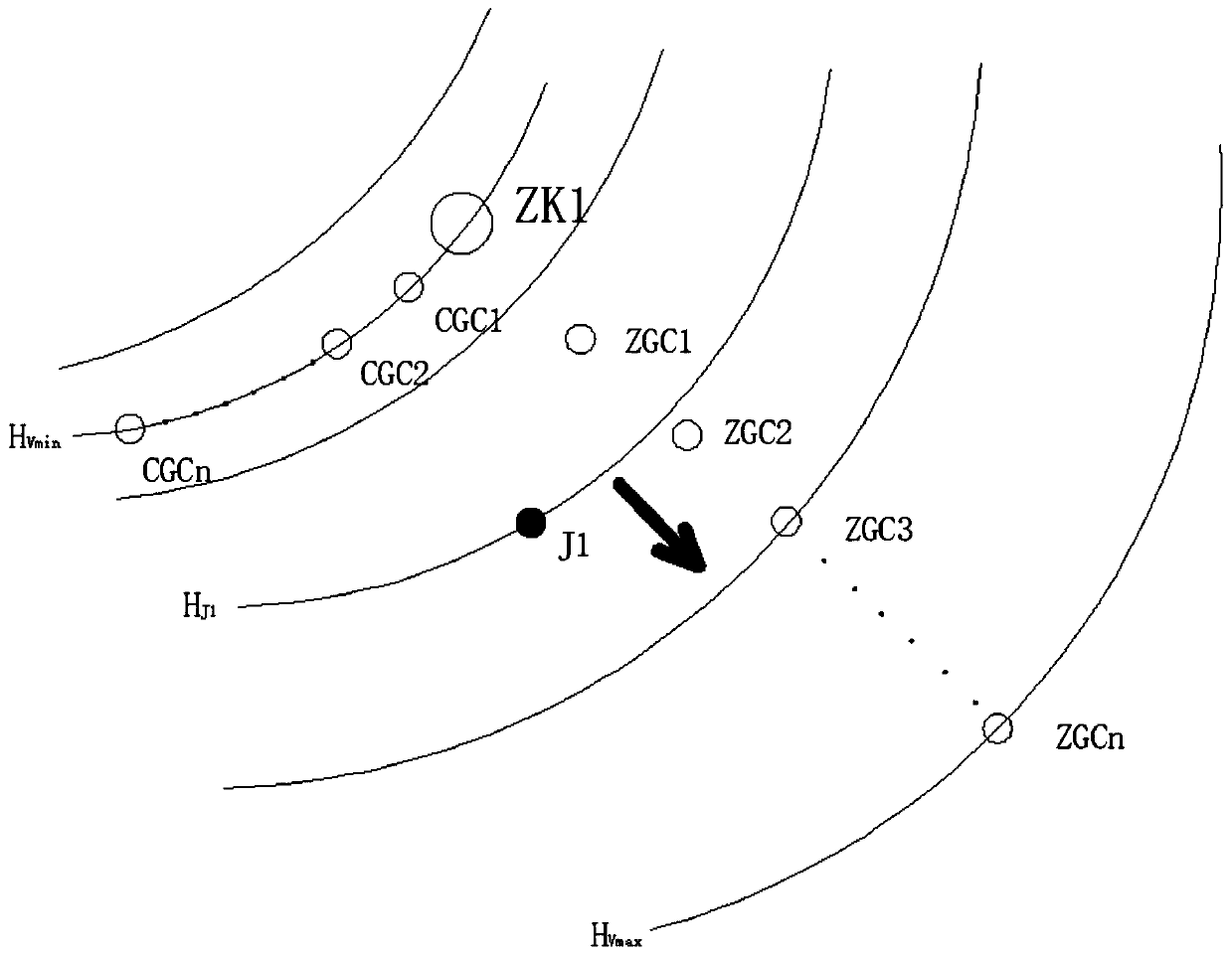
[0051] Step 1.1. Carry out a dispersion test using the porous test method, wherein, such as figure 1 As shown, the main hole of the test is marked as ZK1, the observation holes in the main direction are marked as ZGC1, ZGC2...ZGCn, and the observation holes in the lateral d...


PUM


Abstract

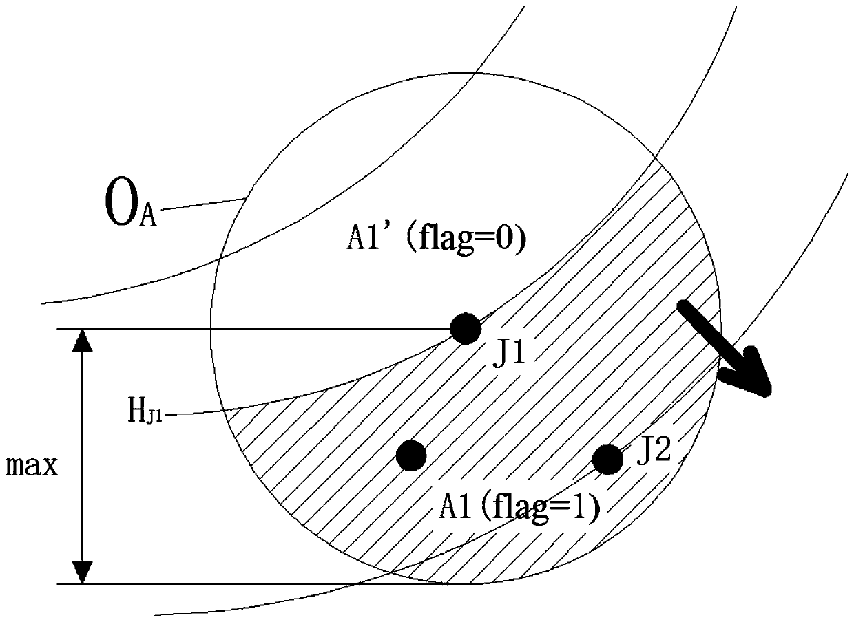
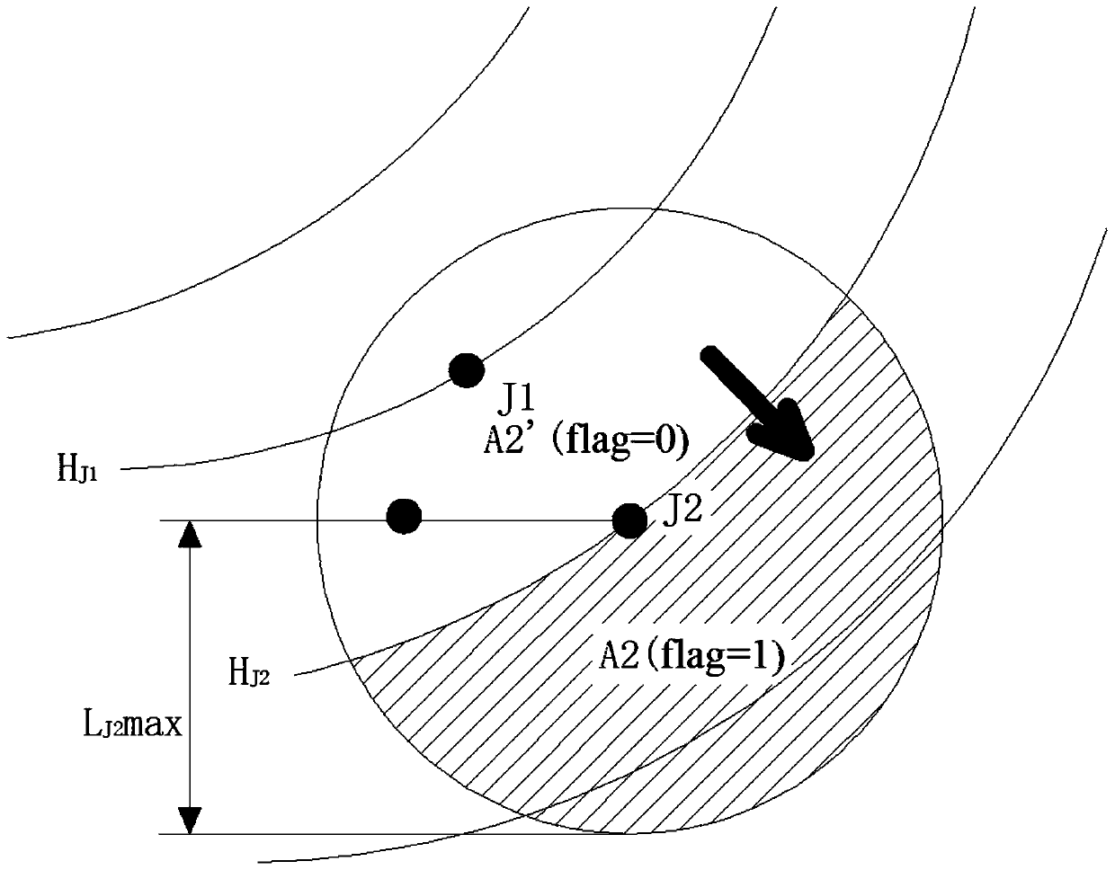
The invention discloses a site groundwater pollutant automatic tracing method. The method comprises the following steps: A, acquiring the shortest time for a pollutant to flow from a test main hole toeach observing hole along a main flow direction, and the longest time for the pollutant to flow from the test main hole to each observing hole along a lateral direction through a dispersion test in order to calculate a maximum possible distance and a minimum possible distance for the pollutant to flow from a pollution source downstream within two monitoring intervals under different hydraulic gradients; B, building a half space model suitable for a target region, partitioning half spaces Ai and Ai', and determining an effective searching half space; C, locking a pollution source range in thehalf space Ai' of which the attribute flag(A)=0; and D, comparing the monitored pollutant with a feature pollutant within the pollution source range for locking the pollution source. According to themethod disclosed by the invention, overlay analysis is performed on a plurality of half space models taking pollutant monitoring holes and possibly-polluted devices as cores through parameters acquired by the dispersion test, so that the aim of tracing is fulfilled by removing interference items according to eliminative induction.

Description


Claims


Application Information

Patent Timeline
Owner SICHUAN INST OF GEOLOGICAL ENG INVESTIGATION
Learn More