Power generation system

A technology for power generation systems and power generation subsystems, applied in engine components, machines/engines, mechanical equipment, etc., can solve problems such as inability to absorb renewable energy power, difficulty in integrating wind power/photovoltaic energy into the grid, and energy structure reform, etc. The effect of sustainable development, improving energy conversion efficiency and saving resources

Active Publication Date: 2019-12-20
STATE GRID HUNAN ELECTRIC POWER +2
View PDF4 Cites 2 Cited by
  • Summary
  • Abstract
  • Description
  • Claims
  • Application Information

AI Technical Summary

Problems solved by technology

With the development of large-scale wind power / photovoltaic resources, my country's wind power / photovoltaic development has maintained a strong momentum of rapid development, but the contradiction between the unconventional development of new energy power generation and the relatively lagging power grid construction has become increasingly obvious, and large-scale is random and problematic. The connection of wind power / photovoltaic energy to the grid with the characteristics of intermittent, anti-regulation and large output fluctuations has a great impact on the voltage stability, transient stability and frequency stability of the system. Wind power / photovoltaic energy is difficult to connect to the grid. Difficulty in consumption and other issues seriously restrict the reform of energy structure
Hydropower units have the characteristics of rapid shutdown, fast adjustment speed, and wide adjustment range. They can perform functions such as peak regulation and frequency modulation in the system. However, conventional hydropower plants and pumped storage power plants have limited roles in large-scale new energy storage and energy conversion. It cannot absorb large-scale renewable energy such as wind power and solar power, and has certain requirements for terrain and geology

Method used


Image

  • Power generation system
  • Power generation system

Examples


Embodiment Construction

[0033] The specific implementation manners of the present invention will be further described in detail below in conjunction with the accompanying drawings and embodiments. The following examples are used to illustrate the present invention, but are not intended to limit the scope of the present invention.

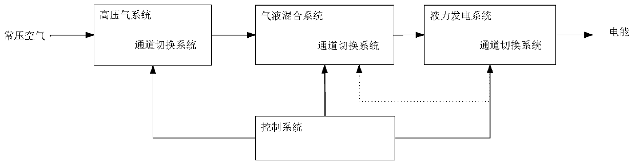
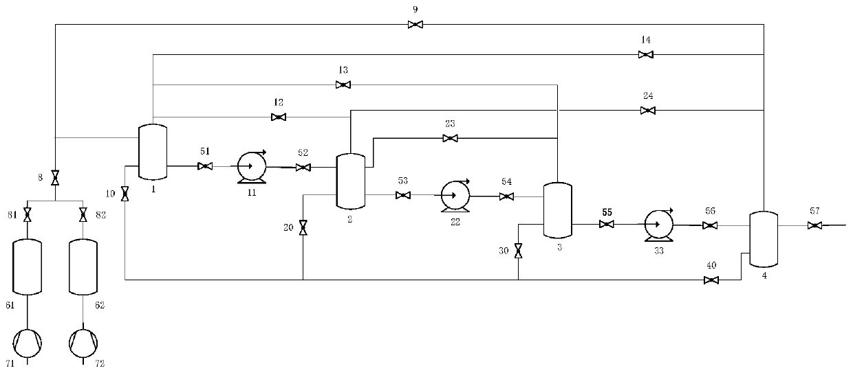
[0034] The invention discloses a power generation system, including a high-pressure gas system, a channel switching system, a gas-liquid mixing system, a hydraulic power generation system and a control system, such as figure 1 As shown, the high-pressure gas system, gas-liquid mixing system, and hydraulic power generation system are connected through the channel switching system and controlled by the control system; the control system changes the operating state of the power generation system, and the operating state of the power generation system is divided into energy storage state and power generation state : In the energy storage state, the power generation system abso...


PUM


Abstract

The invention discloses a power generation system. The power generation system comprises a high-pressure air system, a passage switching system, an air and liquid mixing system, a hydraulic power generation system and a control system; the high-pressure air system, the air and liquid mixing system and the hydraulic power generation system are connected through the passage switching system and arecontrolled by the control system; the control system changes the running state of the power generation system; the running states of the power generation system include an energy storage state and a power generation state; when the power generation system is in the energy storage state, the power generation system is used for absorbing new-energy electric power from an electric grid, transformingthe new-energy electric power into compressed air and storing the compressed air in the high-pressure air system; when the power generation system is in a power generation state, under the effect of the control system, the air energy is transformed into electric energy by virtue of the high-pressure air system, the air and liquid mixing system and the hydraulic power generation system. The power generation system ameliorates the problem that the consumption rate of renewable energy is low because the renewable energy is difficult to supply to the electric grid and is difficult to consume afterbeing supplied to the electric grid.

Description

technical field [0001] The invention relates to the technical field of power generation, in particular to a power generation system. Background technique [0002] In order to increase the proportion of non-fossil energy consumption and ensure the safe supply of electricity and the heating demand of people's livelihood, it is necessary to focus on improving the regulation capability and operating efficiency of the power system, and take multiple measures from the load side, power source side, and grid side, focusing on enhancing system flexibility and adaptability. characteristics, solve the problem of new energy consumption, and promote green development. With the development of large-scale wind power / photovoltaic resources, my country's wind power / photovoltaic development has maintained a strong momentum of rapid development, but the contradiction between the unconventional development of new energy power generation and the relatively lagging power grid construction has bec...

Claims


Application Information

Patent Timeline
Patent Type & Authority Applications(China)
IPC IPC(8): F01D15/10F03B13/00
CPCF01D15/10F03B13/00
Inventor 寇攀高朱光明
Owner STATE GRID HUNAN ELECTRIC POWER
Why Eureka
Try Eureka