


Quick Research
Generate reliable direction feasibility study reports for your R&D in just a few steps.

Technical Q&A
Discover and master advanced knowledge NOW. Basics, ideas, possibilities, all at once.

Find Solutions
As an expert in R&D theories, this can generate solutions to your technical problems instantly.

Evaluate Feasibility
Analyze your overall solution with one click, know your potential R&D risks in advance.

Monitor Landscape
Get weekly tech updates, stay abreast of the latest tech innovations and key insights.
Exhaust butterfly valve detecting device and method
A detection device and a technology for exhaust butterfly valve, applied in the field of valve detection, can solve the problems of poor detection effect and unreasonable device design, and achieve the effects of easy observation and operation, reduced process layout, and small labor input
- Summary
- Abstract
- Description
- Claims
- Application Information
AI Technical Summary
Problems solved by technology
Method used
Image

Examples
Embodiment 1
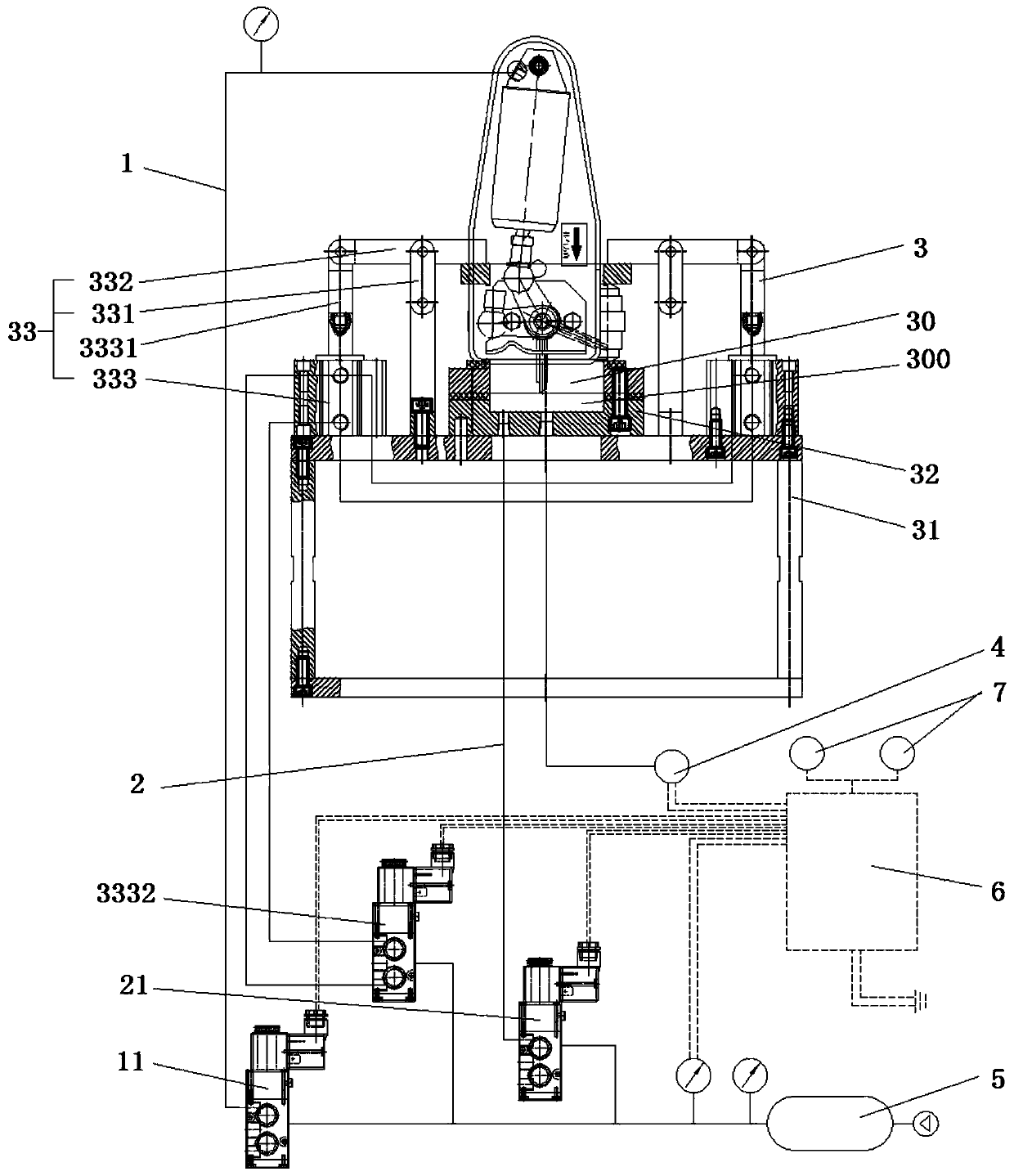
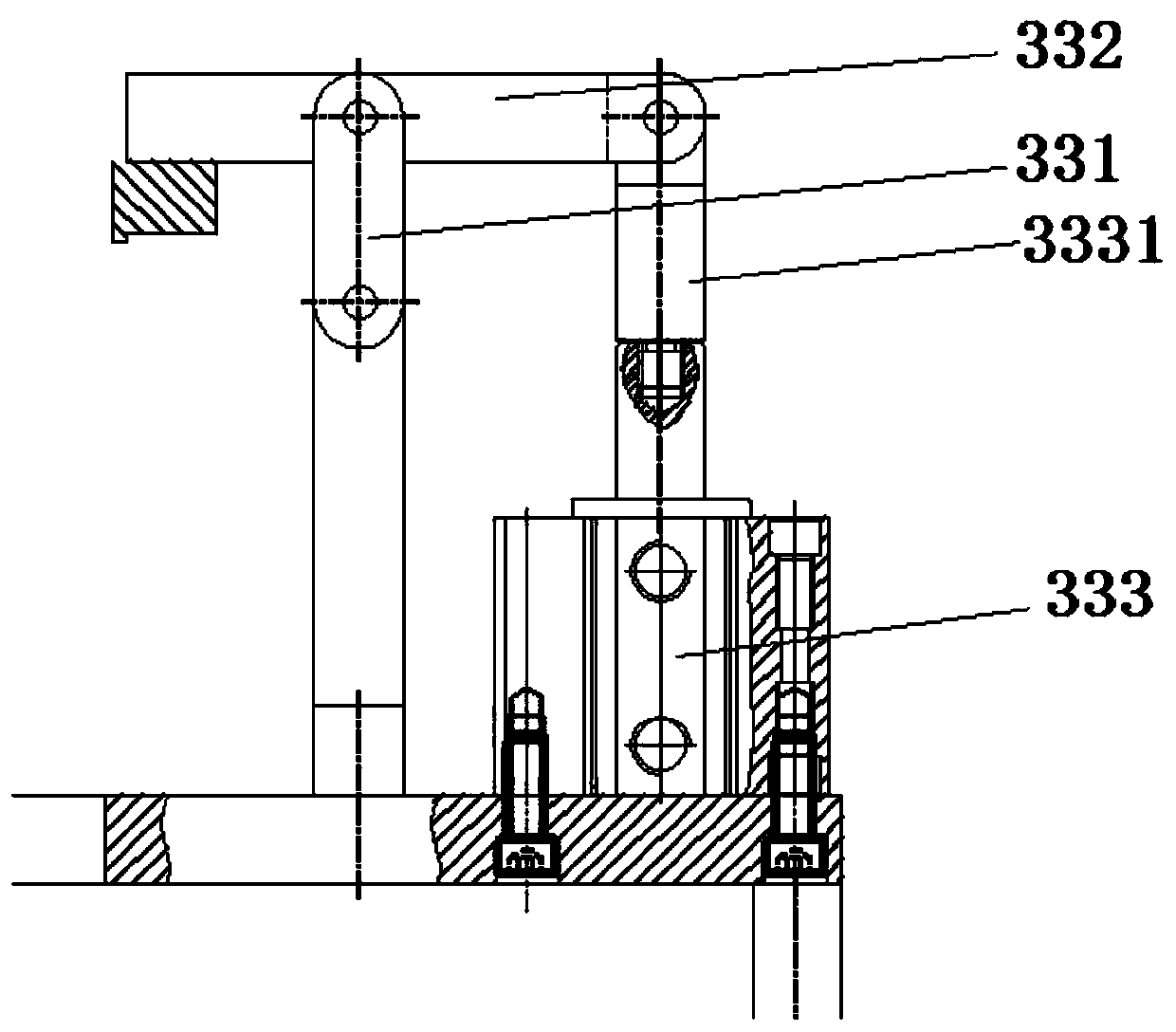
[0028] The exhaust butterfly valve detection device, as shown in the figure, includes an installation and positioning mechanism 3, and the product to be tested is fixed by the installation and positioning mechanism 3. A test slot 30 is provided in the installation and positioning mechanism 3, and the product to be tested is matched with the notch of the test slot 30 And jointly form a sealed cavity 300, the air outlet of the product to be tested communicates with the sealed cavity 300, and also includes a first air channel 1 and a second air channel 2, the first air channel 1 communicates with the air inlet of the product to be detected and inwardly Gas delivery, the second air channel 2 communicates with the air inlet of the sealed cavity 300 and transmits gas inwardly, the sealed cavity 300 is provided with an air outlet, and also includes a pressure detector 4, the pressure detector 4 and the air outlet of the sealed cavity 300 Connect and detect the air pressure change of t...
Embodiment 2
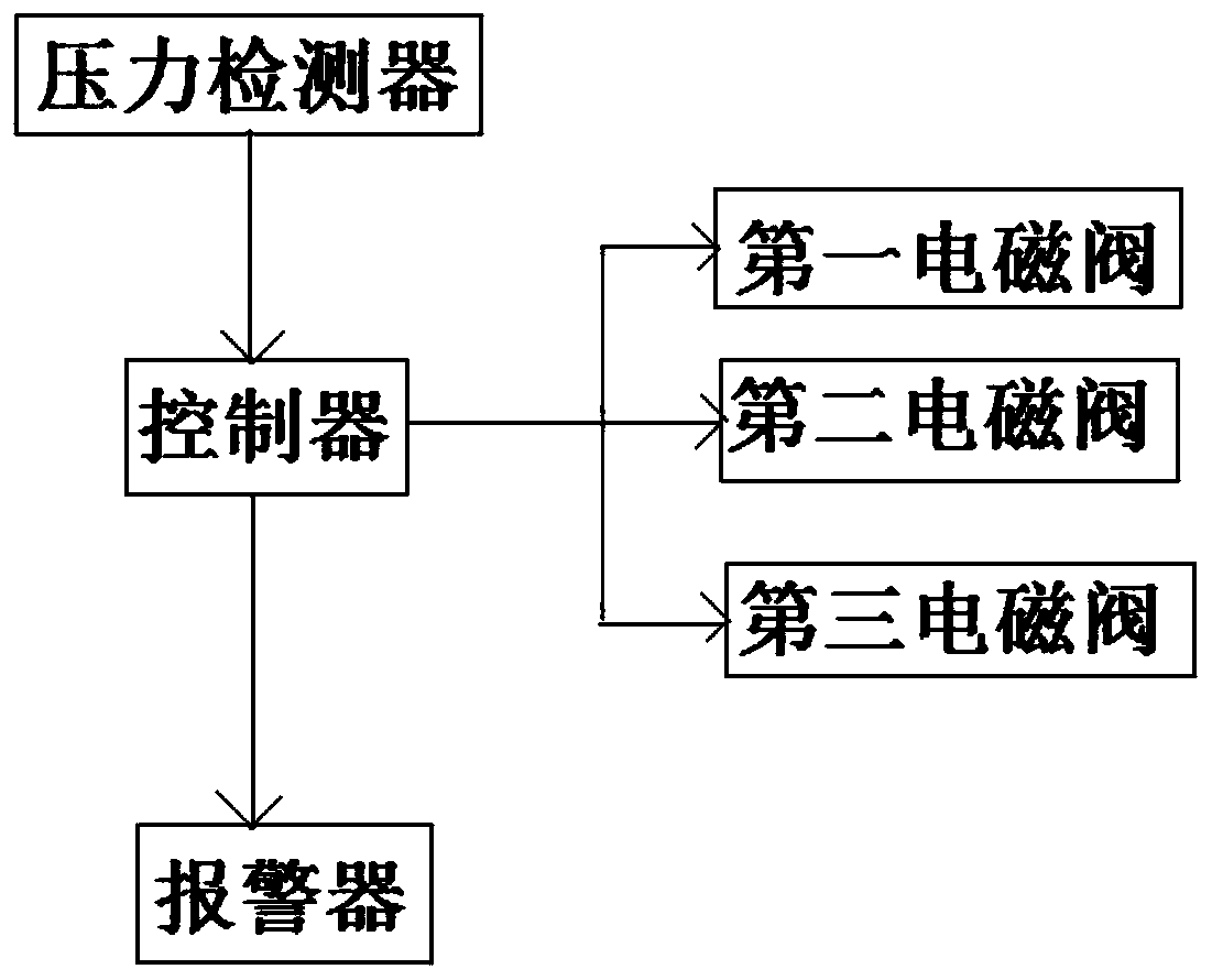
[0036]Same as Embodiment 1, the difference is that it also includes a controller 6, the controller 6 is connected to the pressure detector 4 and performs identification and analysis on the pressure signal sent by the pressure detector 4, the first solenoid valve 11, the second solenoid valve 21 and the The third solenoid valves 3332 are all connected with the controller 6 and controlled by the controller 6 . The controller 6 is a PLC program controller and is connected to a converted 24V power supply. The controller 6 controls the opening and closing of the first solenoid valve 11, the second solenoid valve 21 and the third solenoid valve 3332, thereby controlling the air intake of the product to be detected, the air intake of the product to be detected, and the clamping device 33 purpose of work.
Embodiment 3
[0038] Same as Embodiment 2, the difference is that it also includes an alarm 7, which is connected to the controller 6, and the alarm 7 is controlled by the controller 6 to give a qualified or unqualified alarm.
[0039] The exhaust butterfly valve detection method includes the exhaust butterfly valve detection device, and the specific steps are as follows:
[0040] 1) Connect the air circuit: connect the air inlet above the product to be tested with the air outlet of the first electromagnetic valve 11, connect the air inlet of the two clamping cylinders 3331 with the air outlet of the third electromagnetic valve 3332 to ensure A plurality of clamping cylinders 333 can act synchronously, connect the air inlet of the sealed chamber 300 with the air outlet of the second electromagnetic valve 21, connect the air outlet of the sealed chamber 300 with the pressure detector 4, the first electromagnetic valve 11, the second The solenoid valve 21 and the third solenoid valve 3332 are...
PUM
 Abstract
Description
Claims
Application Information
 - R&D Engineer
- R&D Manager
- IP Professional
- Industry Leading Data Capabilities
- Powerful AI technology
- Patent DNA Extraction
Browse by: Latest US Patents, China's latest patents, Technical Efficacy Thesaurus, Application Domain, Technology Topic, Popular Technical Reports.
© 2024 PatSnap. All rights reserved.Legal|Privacy policy|Modern Slavery Act Transparency Statement|Sitemap|About US| Contact US: help@patsnap.com