
A rotary automatic welding robot and its welding method

An automatic welding and robot technology, applied in welding equipment, auxiliary welding equipment, welding/cutting auxiliary equipment, etc., can solve the problems of complex structure, automatic positioning welding, bulky and bulky, etc., to improve the range of machinability and ensure welding accuracy , Guarantee the effect of processing quality

Active Publication Date: 2020-04-21
江西宜春市华达实业有限公司
View PDF6 Cites 0 Cited by
  • Summary
  • Abstract
  • Description
  • Claims
  • Application Information

AI Technical Summary

Problems solved by technology

[0003] Some existing automatic welding robots are too bulky and complex in structure, and cannot perform all-round automatic positioning welding up and down, left and right, and front and back. The welding torch cannot revolve around the welding workpiece. The workpiece must be used in conjunction with a positioner, and the workpiece must be firmly assembled. On the positioner, and one positioner can only assemble one piece of workpiece, a fixed welding point will be formed after the assembly is completed, resulting in insufficient adjustability of the welding operation

Method used


Image

  • A rotary automatic welding robot and its welding method
  • A rotary automatic welding robot and its welding method
  • A rotary automatic welding robot and its welding method

Examples


Embodiment 1

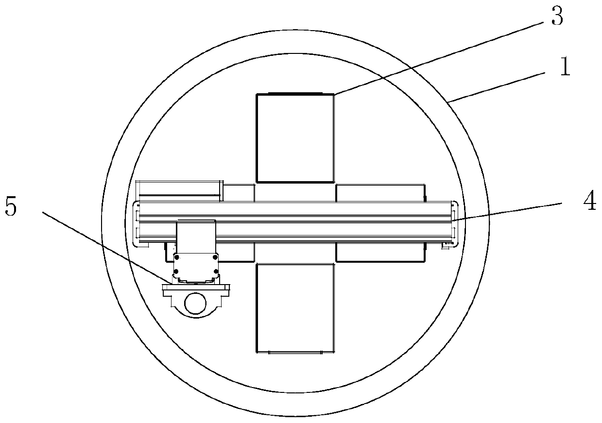
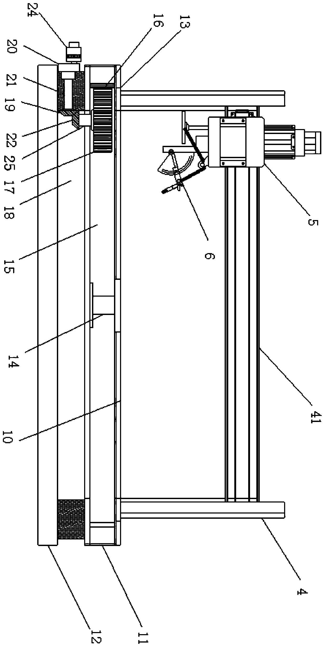
[0036] see figure 1 and figure 2 , a rotary automatic welding robot and welding method thereof, comprising a rotary base 1, a working frame 4 is installed on the rotary base 1, a Y-axis guide rail 41 is installed on the working frame 4, and the Y On the shaft guide rail 41, an adjustment frame 5 is movably installed, and a Z-axis guide rail 51 is installed on the adjustment frame 5, and a welding frame 6 is movably installed on the Z-axis guide rail 51, and the rotary base 1 A bearing platform 10 is fixedly installed on the upper surface of the bearing platform 10, and several jig plates 3 are arranged on the bearing platform 10.

[0037] In this application, the rotary base 1 is the reference plane for the welding operation, the operation frame 4 is the supporting frame for the welding operation, the Y-axis guide rail 41 adjusts the Y-axis coordinate, and the Z-axis guide rail 51 adjusts the Z-axis coordinate. 6 for welding operations. The fixture plate 3 is detachably in...

Embodiment 2

[0047] see Figure 5 , this embodiment serves as a further optimization of the first embodiment, on the basis of which, in order to further improve the precision of the welding process, the present application also adds an adjustment mechanism on the welding frame 6 .

[0048] A fixed base frame 61 is installed on the welding frame 6, a support plate 62 is installed on the top of the fixed base frame 61, and a swing to the frame 63 is installed on the support plate 62 through a movable shaft, and the swing to the frame A welding gun 64 is installed on the 63, an angle measurement plate 65 is also installed on the support plate 62, an arc-shaped groove 66 is arranged on the angle measurement plate 65, and the swing direction frame 63 is installed on the arc-shaped Inside the groove 66.

[0049] The fixed base frame 61 has a built-in adjusting motor, the driving end of the adjusting motor is equipped with a motor shaft 68, and the top of the motor shaft 68 is equipped with an a...


PUM


Abstract

A rotary automatic welding robot, comprising a rotary base (2). An operation machine frame (4) is installed on the rotary base and provided with a Y-axis guide rail (41). An adjusting machine frame (5) is movably installed on the Y-axis guide rail and provided with a Z-axis guide rail (51). A welding frame (6) is movably installed on the Z-axis guide rail. A bearing platform (10) is fixedly installed on an upper surface of the rotary base. The rotary base comprises an upper carrying table (11) and a lower carrying table (12). The upper carrying table is installed on the lower carrying table by means of a supporting rotary shaft (14). A transmission cavity (15) is formed in an inner cavity of the upper carrying table. An annular rack (16) is provided on the inner wall of the transmission cavity. A transmission gear (17) is built in the transmission cavity. The transmission gear is meshed with the annular rack. A stereoscopic machining and adjusting mode is achieved by the whole rotary automatic welding robot, the machining range and machining precision are increased, and the machining quality is ensured. Also provided is a welding method of the rotary automatic welding robot.

Description

technical field [0001] The invention relates to the technical field related to welding technology, in particular to a rotary automatic welding robot and a welding method thereof. Background technique [0002] At present, my country's industrial production needs differentiated welding robots that can efficiently and quickly realize personalized customization and modular combination according to the production requirements of customers, and meet the welding requirements of all-round weldments of different shapes and sizes. [0003] Some existing automatic welding robots are too bulky and complex in structure, and cannot perform all-round automatic positioning welding up and down, left and right, and front and back. The welding torch cannot revolve around the welding workpiece. The workpiece must be used in conjunction with a positioner, and the workpiece must be firmly assembled. On the positioner, and one positioner can only assemble one workpiece, and a fixed welding point i...

Claims


Application Information

Patent Timeline
Patent Type & Authority Patents(China)
IPC IPC(8): B23K37/02B23K37/00
CPCB23K37/00B23K37/0211B23K37/0252
Inventor 张娟娟唐德
Owner 江西宜春市华达实业有限公司
Learn More