
Platform-based expandable rear torsion beam suspension structure

A torsion beam and platform technology, applied in the direction of suspension, elastic suspension, cantilever installed on the pivot, etc., can solve the problems of limited expansion capacity of torsion beam bearing capacity, waste of design and development verification, and heavy vehicle weight. Achieve the effects of reducing unsprung weight, facilitating processing, and reducing workload

Inactive Publication Date: 2019-11-29
HOZON NEW ENERGY AUTOMOBILE CO LTD
View PDF10 Cites 0 Cited by
  • Summary
  • Abstract
  • Description
  • Claims
  • Application Information

AI Technical Summary

Problems solved by technology

The torsion beam suspension and its components that are more common on the market are generally only applicable to a single model, and the scalability between different models on the same platform is poor, which leads to repeated waste of work such as design, development and verification.
At the same time, the torsion beam models currently on the market are mainly in the form of non-closed open beams. This form of torsion beam has a limited load-carrying capacity and expansion capacity. In view of the current research and development status of new energy vehicles, new energy vehicles have no impact on the continuous driving of the whole vehicle. In terms of mileage requirements, the weight of new energy vehicles is larger than that of traditional vehicles (the weight of batteries and motors). When designing the platform architecture of new energy vehicles, it is necessary to consider the platform expansion and the possibility of its load increase.

Method used


Image

  • Platform-based expandable rear torsion beam suspension structure
  • Platform-based expandable rear torsion beam suspension structure
  • Platform-based expandable rear torsion beam suspension structure

Examples


Embodiment 1

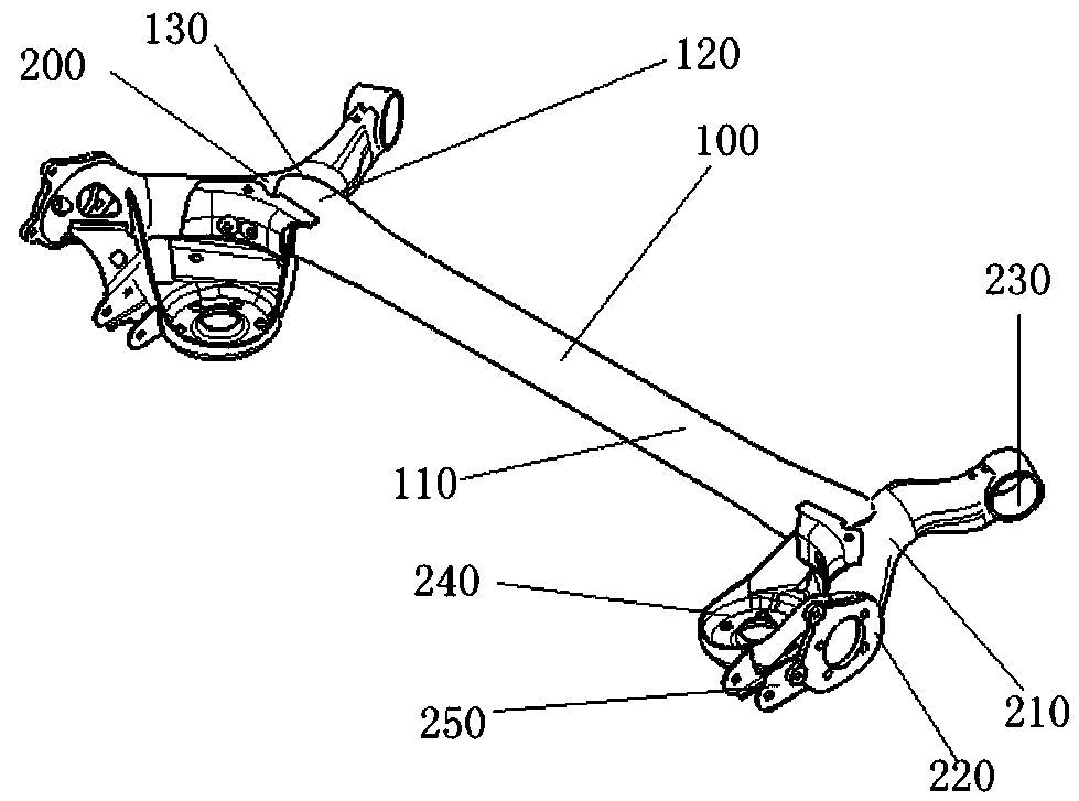
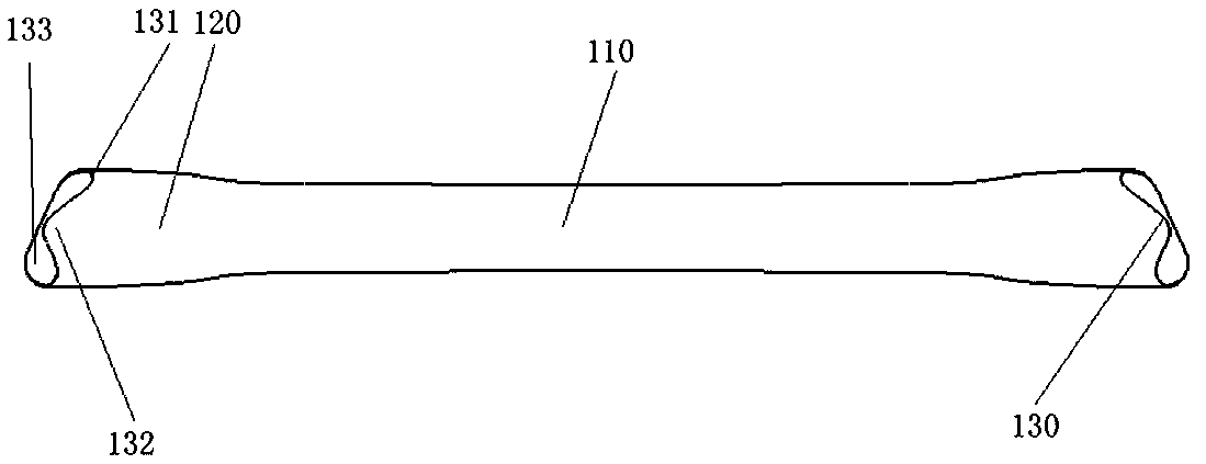
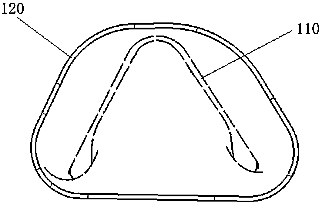
[0027] Such as figure 1 , 2 , 3, 4, and 5 show a platform-based expandable rear torsion beam suspension structure, including a crossbeam 100 and two trailing arm assemblies 200 symmetrically welded to both ends of the crossbeam 100, wherein the trailing arm assembly 200 mainly To bear the function of longitudinal force, the beam 100 mainly plays the role of bearing torsional force, resisting the roll and steering of the vehicle during driving. The crossbeam 100 includes a middle section 110 and an adjustment section 120 integrally connected to both sides of the middle section 110. The section of the adjustment section 120 is a closed trapezoidal shape with rounded corners. This shape can effectively support the weight of the upper vehicle body. Through the closed crossbeam 100, Under the premise of effectively reducing the weight of the rear suspension, it provides greater adjustment and load bandwidth to meet the needs of vehicle performance and load bearing. Its end is a c...

Embodiment 2

[0037] The technical scheme described in embodiment two is similar to embodiment one, and its difference is:

[0038] In this embodiment, in this embodiment, the cross section of the adjustment section 120 is a rounded triangle.


PUM


Abstract

An object of the present invention is to provide a platform-based expandable rear torsion beam suspension structure to solve the problems in the prior art. The platform-based expandable rear torsion beam suspension structure includes a cross beam and longitudinal arm assemblies symmetrically and fixedly connected to both ends of the cross beam. The cross beam includes a middle section and adjustment sections integrally connected to both sides of the middle section. The cross section of each adjustment section is a closed figure. The end portion of each adjustment section is a connection end attached and welded to the surface of the longitudinal arm assembly. The platform-based expandable rear torsion beam suspension structure can provide a better load-bearing capacity in a lightweight state, improves the margin of an index in the design, has good adaptability to different platforms and vehicles of different sizes, reduces the complicated and repeated labor in design and research and development verification, improves design production efficiency and further reduces production cost.

Description

technical field [0001] The invention relates to the technical field of vehicle suspension structures, in particular to an expandable platform-based rear torsion beam suspension structure. Background technique [0002] The torsion beam rear suspension is commonly used in small and medium-sized models because of its small space and cost. Its appearance is similar to the trailing arm type, and there is a crossbeam in the middle that takes into account torsion resistance and support. The longitudinal arms on both sides of the crossbeam are used for positioning in the front and rear directions. . Through the adjustment of the position of the crossbeam, the characteristic parameters such as roll center height, roll stiffness, and roll steering are designed for chassis performance. The torsion beam suspension and its components that are more common on the market are generally only applicable to a single car model, and the scalability between different car models on the same platf...

Claims


Application Information

Patent Timeline
Patent Type & Authority Applications(China)
IPC IPC(8): B60G11/18B60G7/00
CPCB60G7/00B60G11/18B60G2202/136
Inventor 江翁李琳洁王飞杨二平
Owner HOZON NEW ENERGY AUTOMOBILE CO LTD
Learn More