
Motor bracket and centrifugal fan

A centrifugal fan and motor bracket technology, which is applied in the direction of machines/engines, casings/covers/supports, mechanical equipment, etc., can solve the problems of affecting concentricity, poor flatness of motor brackets, and unfavorable fan performance, etc., to achieve improvement Stability, not easy to stretch and deform, and increase the effect of local strength

Active Publication Date: 2022-02-22
FOSHAN SHUNDE MIDEA WASHING APPLIANCES MFG CO LTD
View PDF7 Cites 0 Cited by
  • Summary
  • Abstract
  • Description
  • Claims
  • Application Information

AI Technical Summary

Problems solved by technology

In practical applications, when the motor is fastened by screws, the back plate of the volute is easily stretched and deformed, which makes the flatness of the motor support worse and affects the concentricity of the impeller, the front plate of the volute, the air inlet ring and the motor support. degree, thereby changing the axial and radial clearances between the impeller and the air inlet ring, which is detrimental to the performance of the fan

Method used


Image

  • Motor bracket and centrifugal fan
  • Motor bracket and centrifugal fan
  • Motor bracket and centrifugal fan

Examples


Embodiment Construction

[0029] The following will clearly and completely describe the technical solutions in the embodiments of the present invention with reference to the accompanying drawings in the embodiments of the present invention. Obviously, the described embodiments are only part of the embodiments of the present invention, not all of them. Based on the embodiments of the present invention, all other embodiments obtained by persons of ordinary skill in the art without creative efforts fall within the protection scope of the present invention.

[0030] It should be noted that if there is a directional indication (such as up, down, left, right, front, back...) in the embodiment of the present invention, the directional indication is only used to explain the position in a certain posture (as shown in the accompanying drawing). If the specific posture changes, the directional indication will also change accordingly.

[0031] In addition, if there are descriptions involving "first", "second" and ...


PUM


Abstract

The invention discloses a motor bracket and a centrifugal fan. The motor bracket includes a main body and a recessed portion. The main body is provided with a relief hole, and the relief hole is used for passing through a power supply; the recessed portion is formed by the The main body is recessed along the axial direction of the relief hole, and the groove bottom of the recess is provided with a plurality of installation holes, and the plurality of installation holes are arranged at intervals along the circumference of the relief hole. Holes are used for fixing the motor. The technical solution of the invention can increase the self-strength of the motor support.

Description

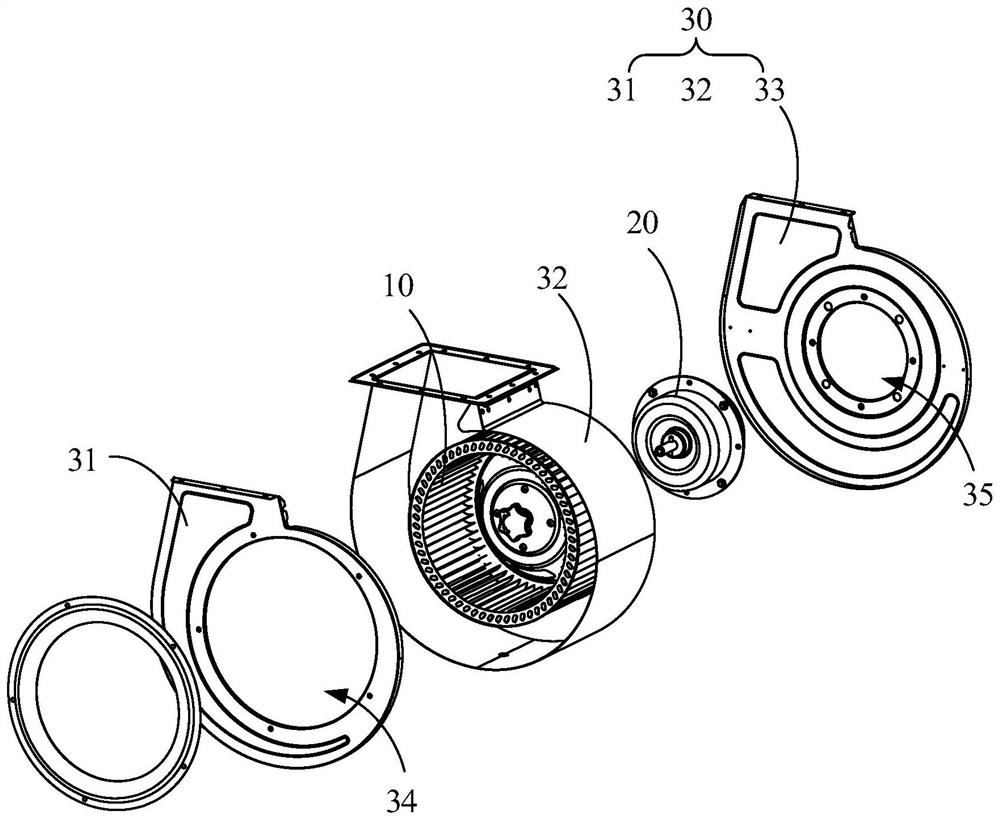
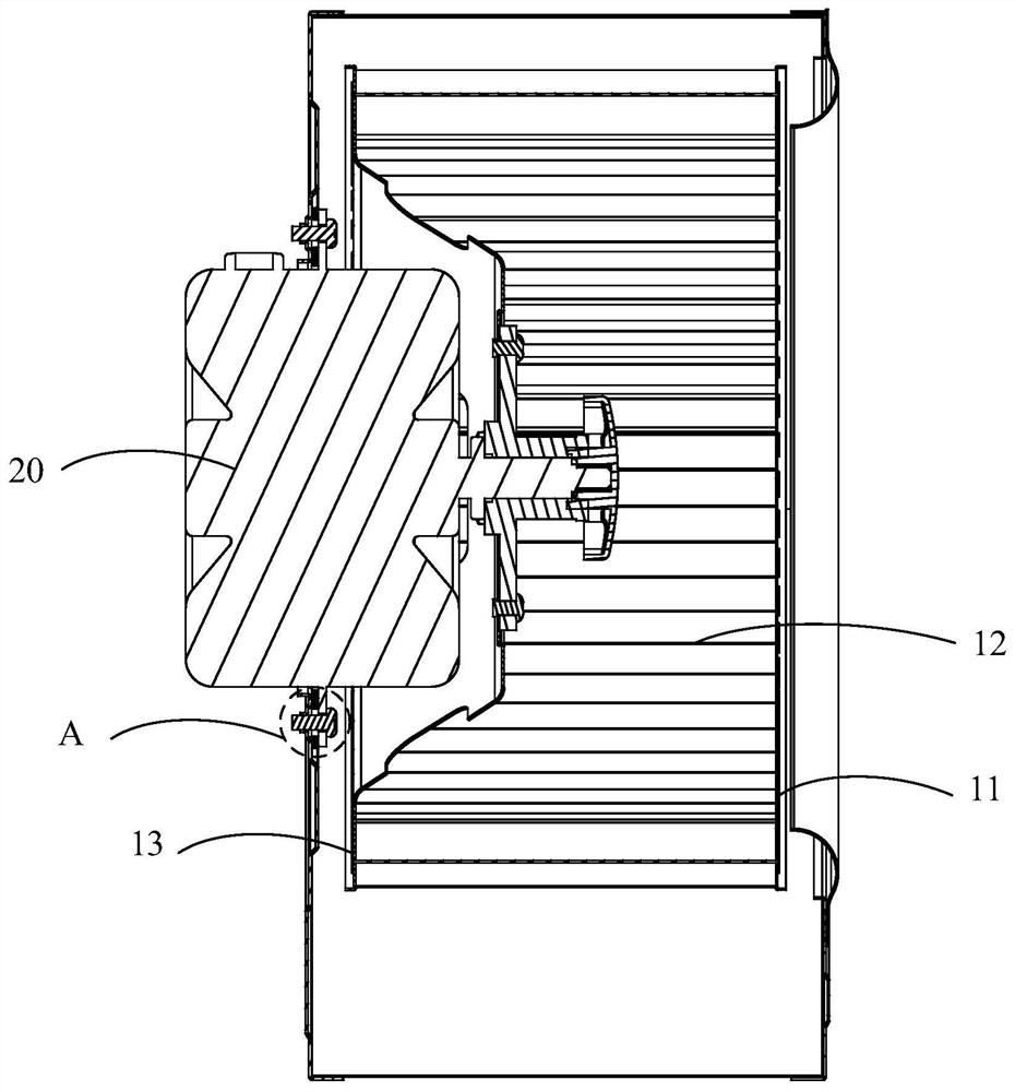
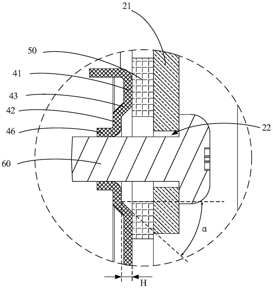
technical field [0001] The invention relates to the field of fans, in particular to a motor support and a centrifugal fan. Background technique [0002] The motor fixing hole in the traditional motor bracket is opened directly on the main plane of the motor bracket, and the motor is fastened by screws. This kind of opening method has higher requirements on the material strength and thickness of the volute back plate. In practical applications, when the motor is fastened by screws, the back plate of the volute is easily stretched and deformed, which makes the flatness of the motor support worse and affects the concentricity of the impeller, the front plate of the volute, the air inlet ring and the motor support. degree, thereby changing the axial and radial clearances between the impeller and the air inlet ring, which is detrimental to the performance of the fan. Contents of the invention [0003] The main purpose of the present invention is to propose a motor bracket aim...

Claims


Application Information

Patent Timeline
Patent Type & Authority Patents(China)
IPC IPC(8): F04D25/08F04D29/00F04D29/42F04D29/62F04D29/66H02K5/24H02K5/04
CPCF04D25/08F04D29/002F04D29/4226F04D29/624F04D29/668H02K5/24H02K5/04
Inventor 霍星凯蒋济武
Owner FOSHAN SHUNDE MIDEA WASHING APPLIANCES MFG CO LTD
Learn More