
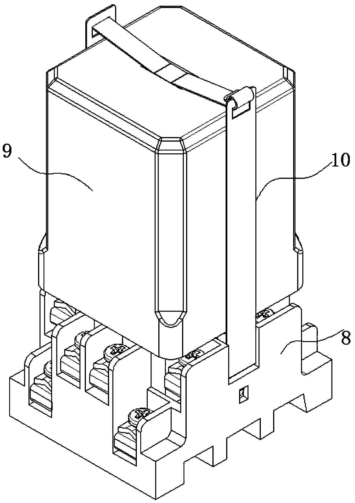
Reed switch relay with protective cover

A technology of dry reed switches and protective covers, which is applied in the direction of relays, electromagnetic relays, detailed information of electromagnetic relays, etc., can solve the problems of uncontrollable channels and high cost, and achieve the effect of reliable waterproof and shockproof performance

Active Publication Date: 2019-11-22
广州株电交通设备有限公司
View PDF8 Cites 0 Cited by
  • Summary
  • Abstract
  • Description
  • Claims
  • Application Information

AI Technical Summary

Problems solved by technology

[0002] The reed switch relay with a protective cover plays a very important role in the control of rail transit signals. The products used in the environment, with the rise and large-scale application of rail transit, control the signals of various intensities of rail transit equipment. It has become a problem that needs to be faced seriously. In the industry, imported products such as Yaskawa from Japan are mostly used, but their cost is expensive and the channels are uncontrollable. In the face of the national rail transit strategy, it is necessary to have domestically produced similar products with high performance and high reliability. An important issue in the domestic industry, especially for the harsh environment of rail transit signal control, a dry reed with a protective cover with fast response time, high sensitivity, long service life, and high reliability is suitable for harsh environments Tube relays are very important

Method used


Image

  • Reed switch relay with protective cover
  • Reed switch relay with protective cover
  • Reed switch relay with protective cover

Examples


Embodiment Construction

[0031] The following will clearly and completely describe the technical solutions in the embodiments of the present invention with reference to the accompanying drawings in the embodiments of the present invention. Obviously, the described embodiments are only some, not all, embodiments of the present invention.

[0032] In describing the present invention, it should be understood that the terms "upper", "lower", "front", "rear", "left", "right", "top", "bottom", "inner", " The orientation or positional relationship indicated by "outside", etc. is based on the orientation or positional relationship shown in the drawings, and is only for the convenience of describing the present invention and simplifying the description, rather than indicating or implying that the referred device or element must have a specific orientation, so as to Specific orientation configurations and operations, therefore, are not to be construed as limitations on the invention.

[0033] refer to Figure ...


PUM


Abstract

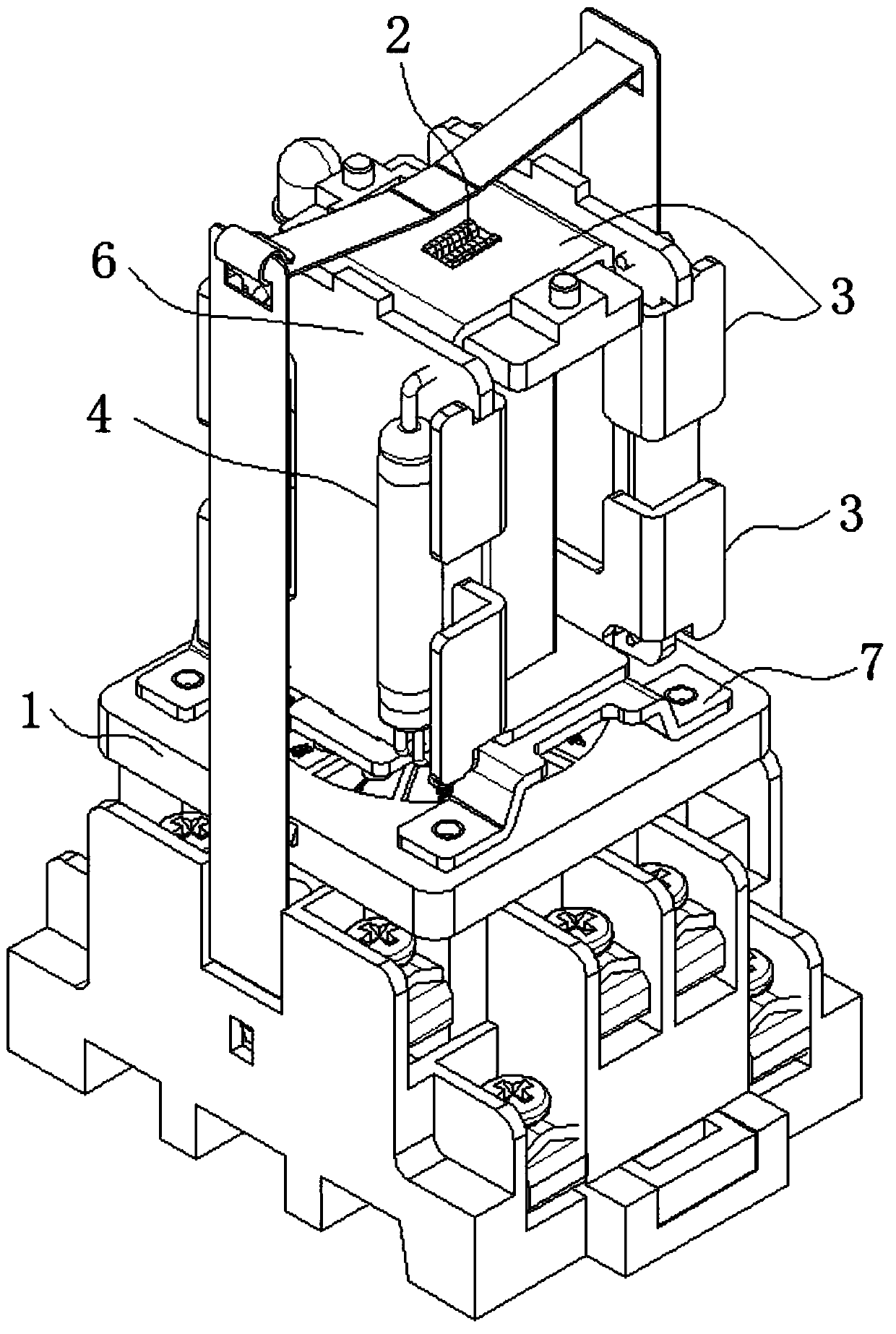
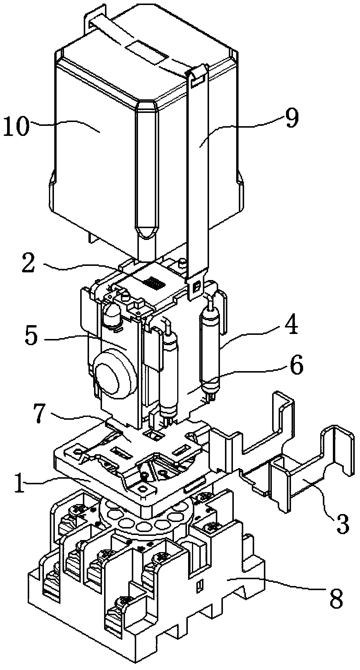
The invention discloses a reed switch relay with a protective cover, and belongs to the field of relays. The invention discloses the reed switch relay with the protective cover. The reed switch relaycomprises the following parts: a wiring base; a pin seat arranged on the wiring base, and a terminal of the pin seat inserted into a terminal hole of the wiring base; an electromagnetic coil arrangedon the pin seat; a reed switch arranged on the pin seat, wherein one end of the reed switch is electrically connected to the terminal of the pin seat, and the other end of the reed switch is connectedwith an external circuit; magnetic conductive sheets arranged at the two ends of the electromagnetic coil, wherein magnetic poles of the magnetic conductive sheets are close to the reed switch; the waterproof protective cover clamped on the wiring base through a clamping piece; after the electromagnetic coil on the pin seat is powered on, magnetic fields are generated at the two ends of a siliconsteel sheet in a coil framework and guided into the eight magnetic poles on the two sides of the coil through the magnetic conductive sheets; the magnetic conductive sheet is a high-magnetic-conductivity pure iron sheet and attracts magnetic materials in the reed switch, the reed switch is switched on, and the control purpose is achieved.

Description

technical field [0001] The invention relates to the technical field of relays, in particular to a reed switch relay with a protective cover. Background technique [0002] The reed switch relay with a protective cover plays a very important role in the control of rail transit signals. The products used in the environment, with the rise and large-scale application of rail transit, signal control of various intensities of rail transit equipment It has become a problem that needs to be faced seriously. In the industry, imported products such as Yaskawa from Japan are mostly used, but their cost is expensive and the channels are uncontrollable. In the face of the national rail transit strategy, it is necessary to have similar products with high performance and high reliability made in China. An important topic in the domestic industry, especially for the harsh environment of rail transit signal control, a dry reed with a protective cover with fast response time, high sensitivity,...

Claims


Application Information

Patent Timeline
Patent Type & Authority Applications(China)
IPC IPC(8): H01H51/28H01H50/44
CPCH01H50/44H01H51/28
Inventor 蒋飞
Owner 广州株电交通设备有限公司
Learn More