
Method for identifying rotary coding switch based on global interrupt trigger

A technology of rotary coding switch and trigger mode, applied in the direction of instruments, computer control, simulators, etc., can solve the problem of misjudgment of rotation direction, inability to distinguish interrupt trigger and other problems

Active Publication Date: 2019-11-22
SICHUAN CHANGHONG ELECTRIC CO LTD
View PDF16 Cites 1 Cited by
  • Summary
  • Abstract
  • Description
  • Claims
  • Application Information

AI Technical Summary

Problems solved by technology

[0011] The technical problem to be solved by the present invention is to propose a method for identifying a rotary encoding switch based on a global interrupt trigger, so as to solve the problem that the MCU that cannot distinguish whether the interrupt trigger is a rising edge or a falling edge is prone to misjudgment of the rotation direction when adapting the rotary switch question

Method used


Image

  • Method for identifying rotary coding switch based on global interrupt trigger
  • Method for identifying rotary coding switch based on global interrupt trigger
  • Method for identifying rotary coding switch based on global interrupt trigger

Examples


Embodiment Construction

[0044] The present invention aims to propose a method for identifying a rotary encoding switch based on a global interrupt trigger to solve the problem that an MCU that cannot distinguish whether an interrupt trigger is a rising edge or a falling edge is prone to misjudgment of the rotation direction when adapting a rotary switch. The core idea is: connect the two pulse signal output pins of the rotary encoding switch to the corresponding hardware of the two GPIO ports of the MCU, and use the GPIO pins of the MCU to detect a change in the voltage signal to trigger a global interrupt. According to the two GPIO The interrupt sequence between the ports, combined with the reset mechanism and the interrupt filtering mechanism, filters the interference factors, so that the MCU can accurately identify the rotation direction of the knob and respond to related commands accurately and sensitively.

[0045] In terms of specific implementation, the method for identifying rotary encoding sw...


PUM


Abstract

The invention relates to the identification technology of a rotary coding switch, discloses a method for identifying the rotary coding switch based on global interrupt trigger and solves a problem ofeasily-generated error determination of a rotation direction when an MCU incapable of distinguishing whether the interrupt trigger is a rising edge or a falling edge adapts to a rotary switch. The method comprises steps that a, two pulse signal output pins of the rotary coding switch are connected with corresponding hardware of two GPIO ports of an MCU; b, an interrupt trigger mode of the two GPIOports of the MCU are set to be a global interrupt trigger; c, when a knob of the rotary coding switch is turned, interrupt trigger states of the two GPIO ports are respectively recorded by the MCU through two interrupt triggers according to set interrupt trigger recording rules; and d, the rotation direction of the knob is identified by the MCU from the recorded interrupt data according to set identification rules.

Description

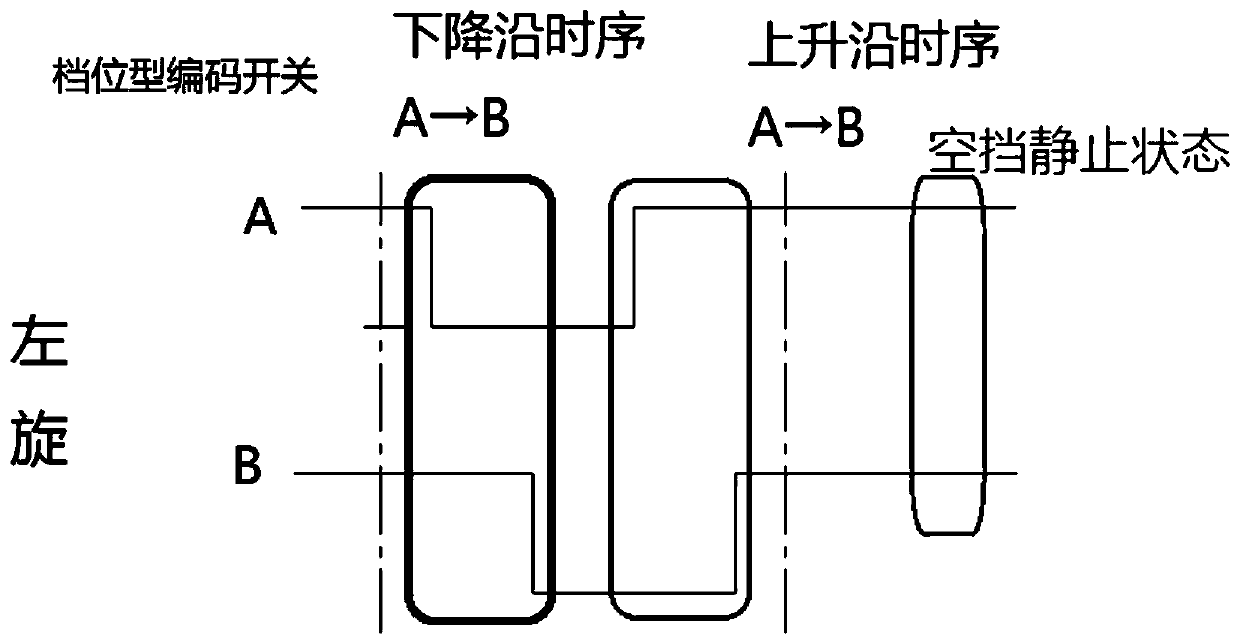
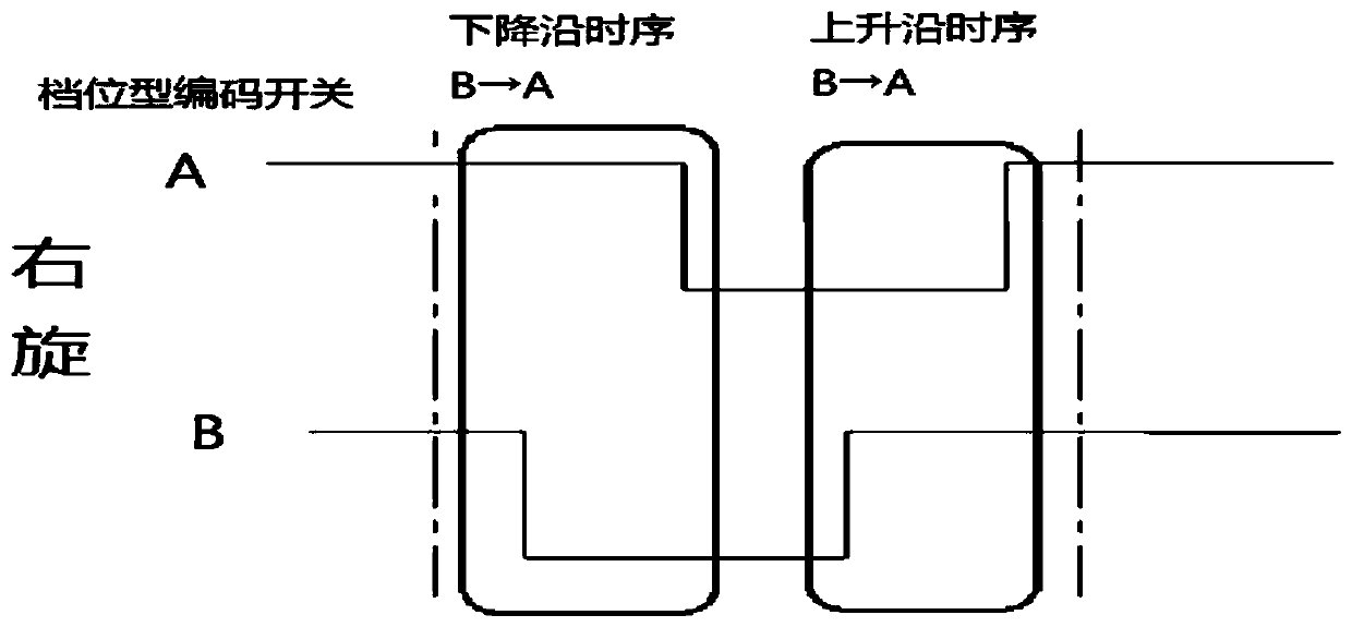
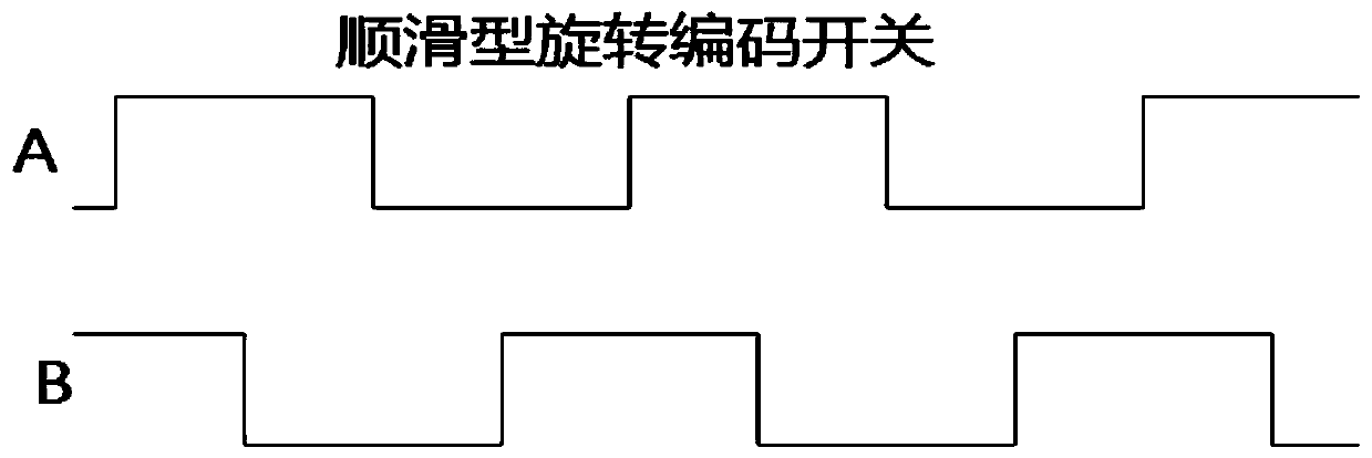
technical field [0001] The invention relates to an identification technology of a rotary encoding switch, in particular to a method for identifying a rotary encoding switch based on global interrupt triggering. Background technique [0002] With the development of electronic technology, various MCUs have become the information and control processing center of electronic products. It can detect the voltage status through the high-speed GPIO port, and can record the detected voltage changes in an interrupt-triggered manner, with an accuracy of us level. . [0003] The rotary encoding switch replaces the traditional resistance potentiometer as a commonly used control device. Its two pins are connected to the internal shrapnel, and the contacts are regularly contacted and disconnected to generate a pulse signal. The pulse signal follows the left rotation. and right-handed produce a different timing relationship. The working principle of the knob with gears is analyzed below: ...

Claims


Application Information

Patent Timeline
Patent Type & Authority Applications(China)
IPC IPC(8): G05B19/042
CPCG05B19/0423G05B2219/21068G05B2219/21126
Inventor 翟让海王圣富
Owner SICHUAN CHANGHONG ELECTRIC CO LTD
Learn More