
Mold core structure of micro-foaming injection mold

An injection mold and micro-foaming technology, applied in the field of mold parts, can solve the problems of more waste of mold core materials, waste of mold core replacement, single mold core structure, etc., to save raw material costs, processing costs, and stable position. Effect

Active Publication Date: 2019-11-22
HANGZHOU POLYTECHNIC
View PDF6 Cites 0 Cited by
  • Summary
  • Abstract
  • Description
  • Claims
  • Application Information

AI Technical Summary

Problems solved by technology

In actual production, the mold core can bring different benefits, but the mold core structure is relatively single, and this kind of mold core wastes more mold core materials during the production process, especially only the mold core needs to be replaced, other parts When there is no need to replace, the replacement of the entire mold core is a waste

Method used


Image

  • Mold core structure of micro-foaming injection mold
  • Mold core structure of micro-foaming injection mold
  • Mold core structure of micro-foaming injection mold

Examples


Embodiment Construction

[0032] In order to make the purpose, technical solution and advantages of the technical solution of the present invention clearer, the technical solutions of the embodiments of the present invention will be clearly and completely described below in conjunction with the drawings of specific embodiments of the present invention. The same reference numerals in the figures represent the same parts. It should be noted that the described embodiments are some of the embodiments of the present invention, but not all of the embodiments. Based on the described embodiments of the present invention, all other embodiments obtained by persons of ordinary skill in the art without creative efforts shall fall within the protection scope of the present invention.

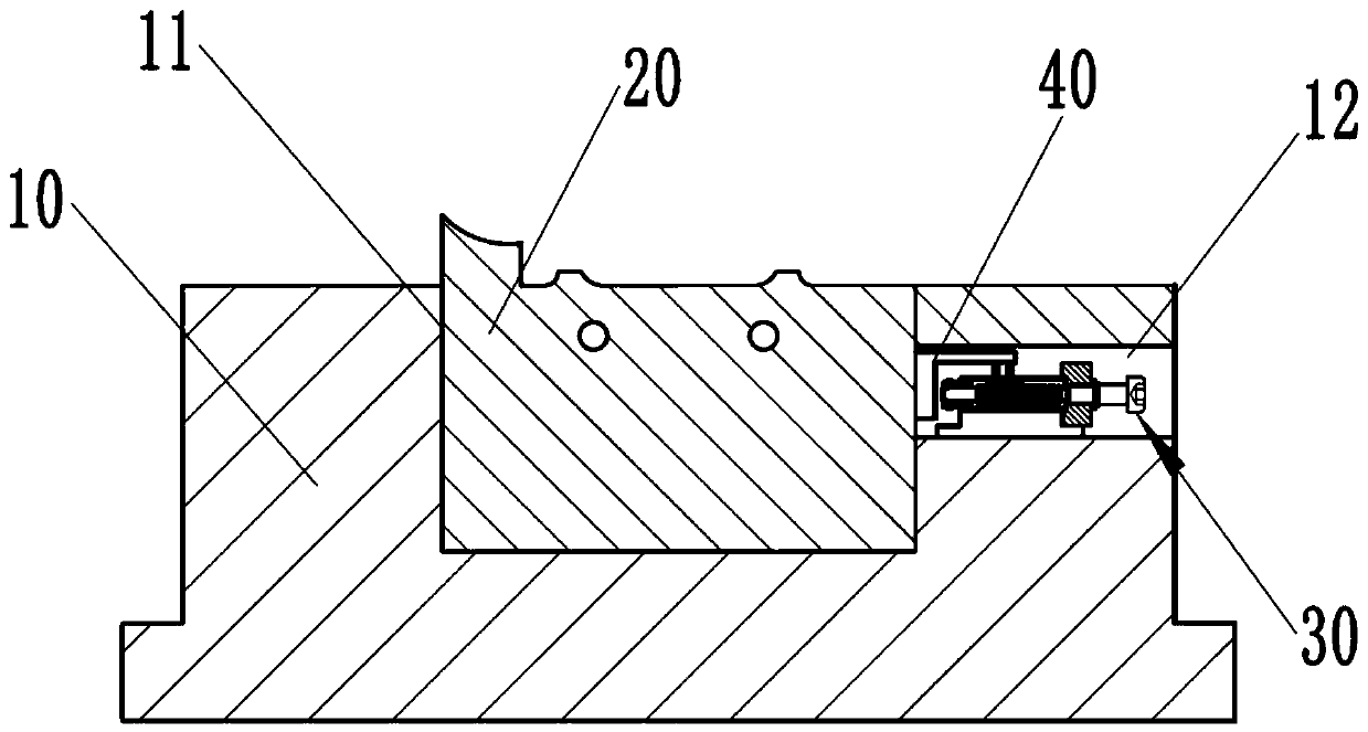
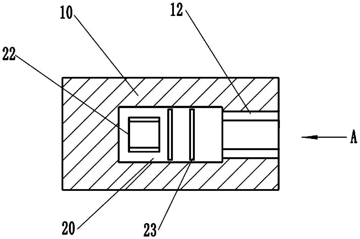
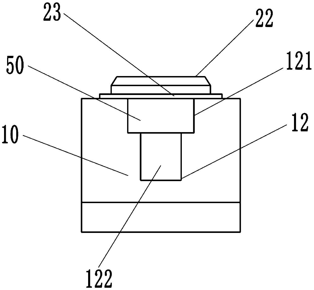
[0033] See attached Figure 1 to Figure 7 ,Such as Figure 7 As shown, the microfoaming injection mold includes an upper template 71 and a lower template 74, a fixed mold 72 is installed below the upper template 71, a movable mold ...


PUM


Abstract

The invention provides a mold core structure of a micro-foaming injection mold. The mold core structure comprises a mold core body and a sub-mold core, wherein one side of the mold core body is provided with one side groove; a clamping device and a top plate are arranged in the side groove; the clamping device comprises a base, a clamping piece body, a sliding base and a screw rod; the clamping piece body is fixedly arranged on the upper surface of the base; a fixing base is fixed on the base; a connecting base is fixed on the upper surface of the base; one end of the screw rod is movably arranged on the fixing base; and the other end of the screw rod is movably arranged on a connecting base. According to the mold core structure of the micro-foaming injection mold, the mold core body is detachably connected with the sub-mold core, and the clamping device is arranged in the side groove of the mold core body, so that only the sub-mold core needs to be replaced, the replacement is more convenient, and the sub-mold core can be tightened during installing.

Description

technical field [0001] The invention relates to mold parts, in particular to a core structure of a microfoaming injection mold. Background technique [0002] In the manufacture of micro-foaming injection molds, the matching template structure of the mold and the mold core structure of the mold are prepared and processed separately, that is, the mounting holes for positioning are processed on the mold core first, and then the processed inserts are combined with The templates cooperate with each other to form the overall structure of the mold. In actual production, the mold core can bring different benefits, but the mold core structure is relatively single, and this kind of mold core wastes more mold core materials during the production process, especially only the mold core needs to be replaced, other parts When there is no need to replace, the replacement of the entire mold core is a waste. [0003] For this reason, how to improve the structure of the mold core, realize ba...

Claims


Application Information

Patent Timeline
Patent Type & Authority Applications(China)
IPC IPC(8): B29C45/26B29C33/30B29C44/58
CPCB29C44/58B29C45/2602B29C45/2673
Inventor 谭小红
Owner HANGZHOU POLYTECHNIC
Learn More