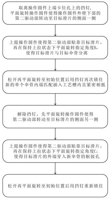
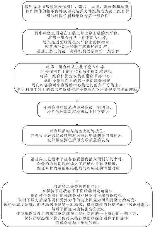
Disassembly and assembly process of umbrella rib and upper nest
A technology of umbrella ribs and craftsmanship, applied in the field of umbrellas, can solve the problems of user inconvenience, difficult operation, scratching fingers, etc., and achieve the effect of overcoming low efficiency, low artificial influence, and high tensile strength
- Summary
- Abstract
- Description
- Claims
- Application Information
AI Technical Summary
Problems solved by technology
Method used
Image


Examples
Embodiment Construction
[0038] The present invention will be further described below in conjunction with the accompanying drawings:
[0039] like Figure 3-11 As shown, this embodiment provides an improved upper nest structure for an umbrella, which includes a nest base 10 and a nest cover 20 .
[0040] In this embodiment, the top center of the nest seat 10 is provided with a seat hole 11 that penetrates up and down and an operating circular piece 30 arranged concentrically on the periphery of the seat hole 11 , and the top edge of the nest seat 10 is provided with a circular ring in cross section. The chute 12 is shaped and arranged concentrically with the seat hole 11 and a plurality of accommodating grooves 13 are arranged circumferentially at equal intervals and communicated with the chute 12 .
[0041] Between the operating circular piece 30 and the chute 12 are circumferentially spaced equidistantly spaced sliding sheets 40 that match the number of the accommodating grooves 13 . Each sliding s...
PUM
 Abstract
Description
Claims
Application Information
 - R&D
- Intellectual Property
- Life Sciences
- Materials
- Tech Scout
- Unparalleled Data Quality
- Higher Quality Content
- 60% Fewer Hallucinations
Browse by: Latest US Patents, China's latest patents, Technical Efficacy Thesaurus, Application Domain, Technology Topic, Popular Technical Reports.
© 2025 PatSnap. All rights reserved.Legal|Privacy policy|Modern Slavery Act Transparency Statement|Sitemap|About US| Contact US: help@patsnap.com