
Patsnap Eureka
For R&D, Patsnap Eureka makes reading and utilizing patents & technical documents easy.
Patsnap Eureka AIR
Designed for self-driven R&D workflows. Generate viable solutions, solve complex R&D challenges, empower your innovation with AI.

Patsnap Eureka Materials
Designed for material experts only. Revolutionize your material R&D, from search, analyze, to developing new materials.

TechResearch
Generate reliable direction feasibility study reports for your R&D in just a few steps.

TechSeek
Discover and master advanced knowledge NOW. Basics, ideas, possibilities, all at once.

TechMind
As an expert in R&D Theories, TechMind can generates customized viable solutions instantly.

TechRisk
Analyze your overall solution with one click, know your potential R&D risks in advance.

TechMonitor
Get weekly tech updates, stay abreast of the latest tech innovations and key insights.
Positioning device for dry-type motor rotor hot jacket
A technology of motor rotor and positioning device, which is applied in the manufacture of stator/rotor body, etc., which can solve problems such as shaking, inconvenient locking of motor rotor, inconvenient positioning and locking of motor rotor, etc., and achieves the effect of occupying less space
- Summary
- Abstract
- Description
- Claims
- Application Information
AI Technical Summary
Problems solved by technology
Method used
Image


Examples
Embodiment 1
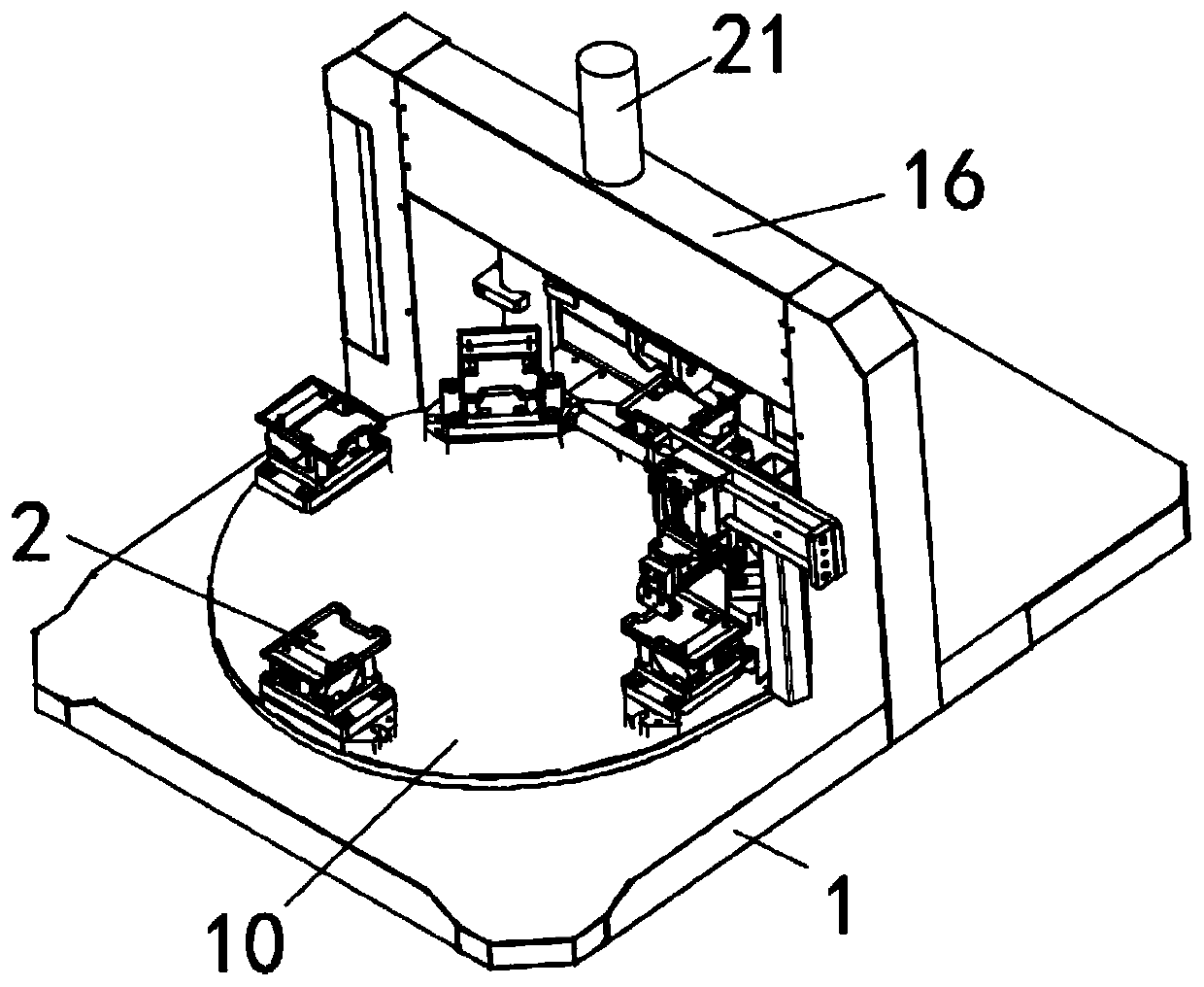
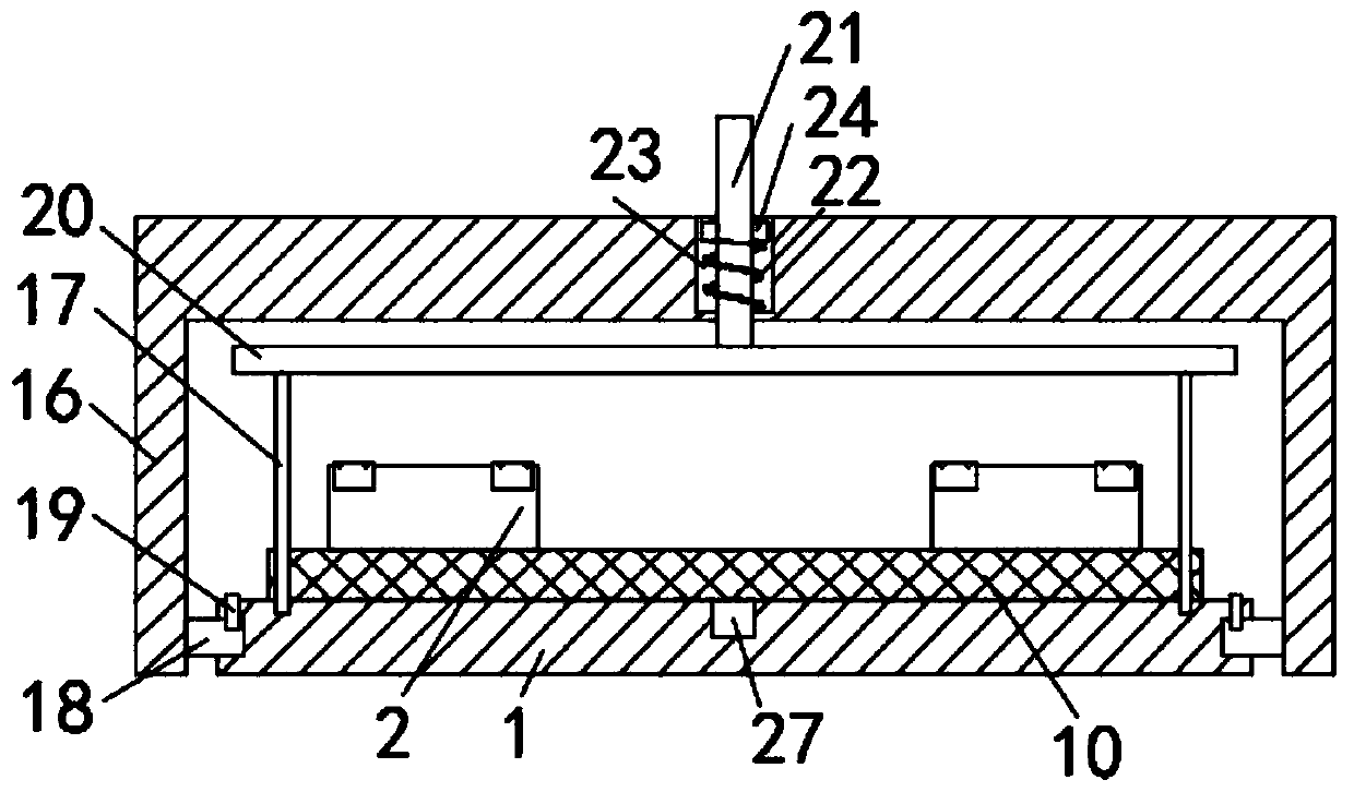
[0040] A positioning device for dry-type motor rotor shrink fit, including a bottom plate 1 and at least one set of positioning components 2 rotationally connected on the bottom plate 1; the positioning component 2 includes a fixed clamping plate 3, a moving clamping plate 4 and a bearing plate 5;
[0041] The lower end of the fixed clamping plate 3 is vertically fixedly connected with a fixed plate 6, and the fixed plate 6 is rotatably connected to the upper surface of the bottom plate 1;
[0042] The movable clamping plate 4 is connected above the fixed plate 6 through an adjustment mechanism;
[0043] The carrying plate 5 is symmetrically fixedly connected to the left and right side walls of the fixed clamping plate 3, and the carrying plate 5 is located between the movable clamping plate 4 and the fixed clamping plate 3, and the lower end of the carrying plate 5 faces upwards to provide an accommodating space 7. The upper end surface of the bearing plate 5 is provided with...
Embodiment 2
[0052] A dry-type motor rotor 28 shrink-fit positioning device, including a bottom plate 1 and at least one set of positioning components 2 rotatably connected on the bottom plate 1; the positioning component 2 includes a fixed clamping plate 3, a moving clamping plate 4 and a bearing plate 5;
[0053] The lower end of the fixed clamping plate 3 is vertically fixedly connected with a fixed plate 6, and the fixed plate 6 is rotatably connected to the upper surface of the bottom plate 1;
[0054] The movable clamping plate 4 is connected above the fixed plate 6 through an adjustment mechanism;
[0055] The carrying plate 5 is symmetrically fixedly connected to the left and right side walls of the fixed clamping plate 3, and the carrying plate 5 is located between the movable clamping plate 4 and the fixed clamping plate 3, and the lower end of the carrying plate 5 faces upwards to provide an accommodating space 7. The upper end surface of the bearing plate 5 is provided with a p...
PUM
 Abstract
Description
Claims
Application Information
 - R&D Engineer
- R&D Manager
- IP Professional
- Industry Leading Data Capabilities
- Powerful AI technology
- Patent DNA Extraction
Browse by: Latest US Patents, China's latest patents, Technical Efficacy Thesaurus, Application Domain, Technology Topic, Popular Technical Reports.
© 2024 PatSnap. All rights reserved.Legal|Privacy policy|Modern Slavery Act Transparency Statement|Sitemap|About US| Contact US: help@patsnap.com