
Unmanned cooperative detection method

A detection method and unmanned technology, applied in radio wave measurement systems, measurement devices, geophysical measurement and other directions, can solve problems such as easy to cause safety accidents, obstacles that cannot be detected by vehicles, and body obstructions.

Active Publication Date: 2019-11-15
TONGJI UNIV
View PDF6 Cites 3 Cited by
  • Summary
  • Abstract
  • Description
  • Claims
  • Application Information

AI Technical Summary

Problems solved by technology

[0002] Unmanned driving technology mainly obtains the external information of the vehicle through sensors, so as to construct a scene model for analysis and decision-making in the digital world. Obstacles in the detection blind zone cannot be detected by the vehicle, this phenomenon is more obvious in the unmanned driving environment
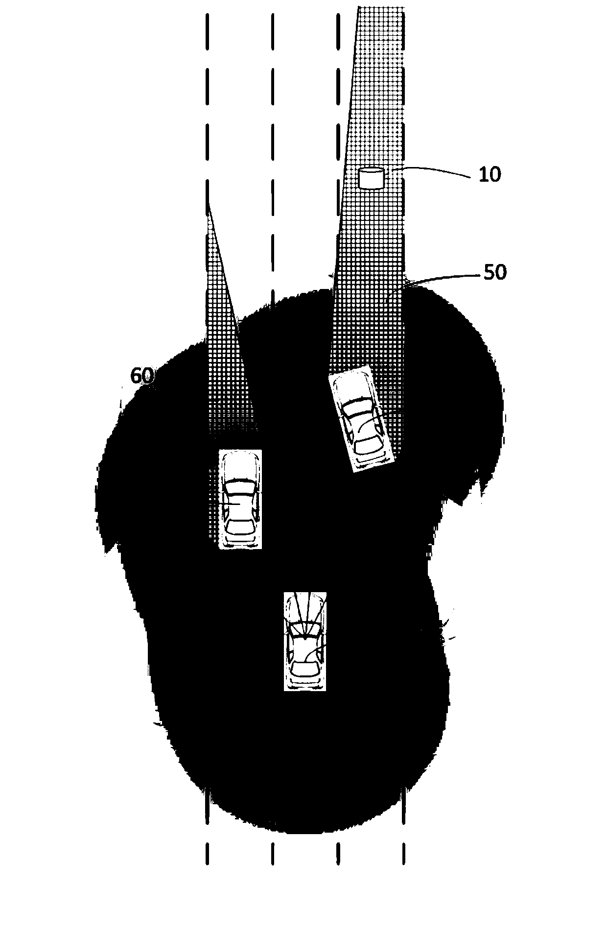
[0003] The relative movement of the vehicles during the movement, due to the short distance between each other and the obstruction of the body, the detection range of the vehicle sensor is limited, and it is easy to generate a detection blind spot. Once there is an obstacle in the detection blind spot, the vehicle cannot obtain it in advance. Detect obstacle information in the blind area, so it is very easy to cause safety accidents

Method used


Image

  • Unmanned cooperative detection method
  • Unmanned cooperative detection method
  • Unmanned cooperative detection method

Examples


Embodiment Construction

[0080] The present invention will be described in detail below in conjunction with the accompanying drawings and specific embodiments.

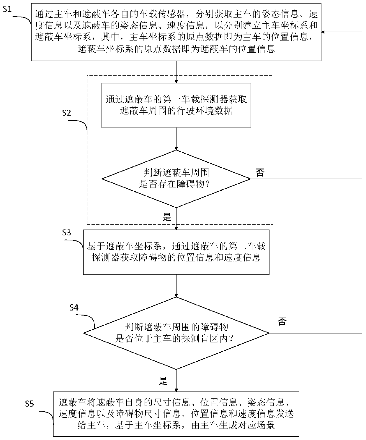
[0081] Such as figure 1 As shown, an unmanned cooperative detection method includes the following steps:

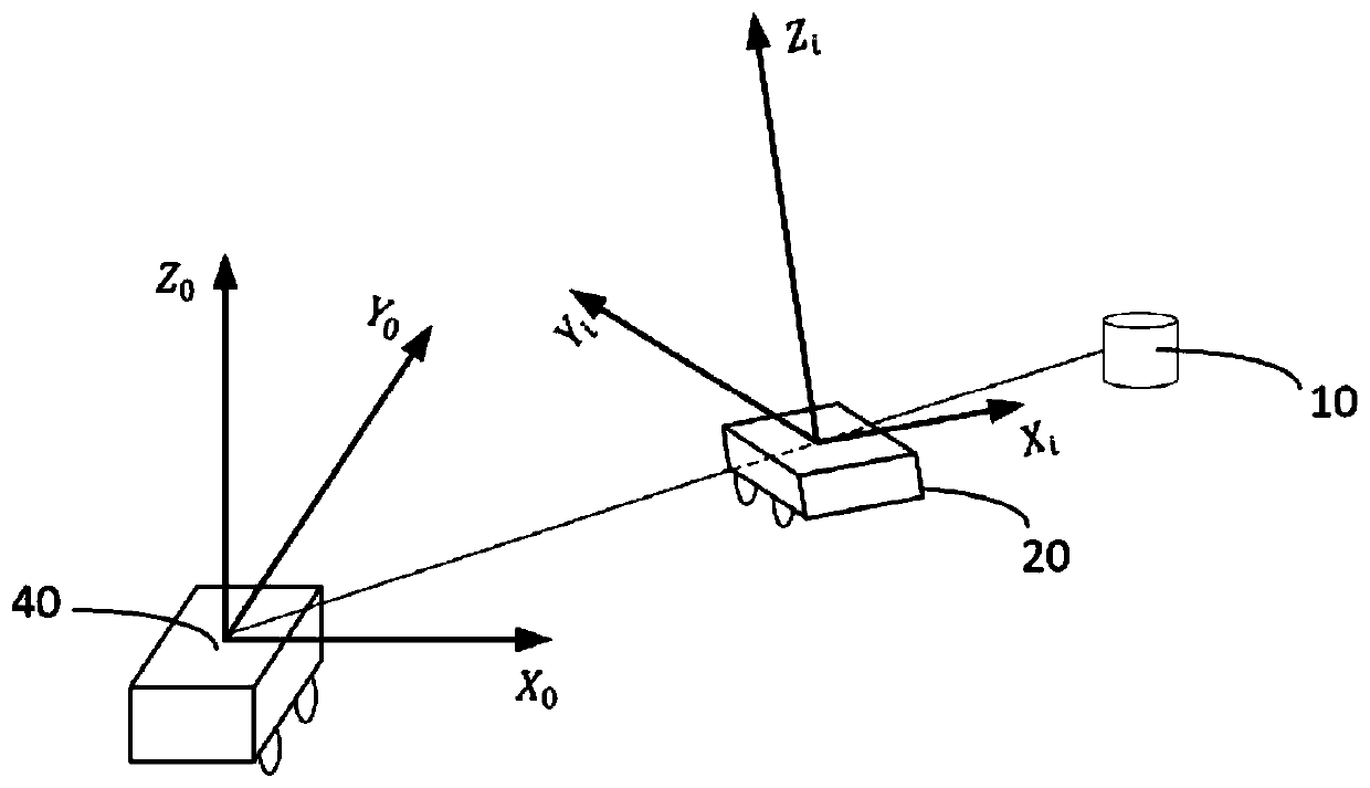
[0082] S1. Obtain the attitude information and speed information of the main vehicle and the attitude information and speed information of the shelter vehicle through the respective on-board sensors of the main vehicle and the shielding vehicle, so as to respectively establish the coordinate system of the main vehicle and the coordinate system of the shielding vehicle. Among them, the main vehicle The origin data of the coordinate system is the location information of the main vehicle, and the origin data of the masking vehicle coordinate system is the location information of the masking vehicle;

[0083] S2. Obtain the driving environment data around the sheltering car through the first vehicle-mounted detector of the sheltering car, a...


PUM


Abstract

The invention relates to an unmanned cooperative detection method, comprising the steps: S1, respectively obtaining the related information of a main vehicle and a shielding vehicle through a vehicle-mounted sensor, and respectively building a main vehicle coordinate system and a shielding vehicle coordinate system; S2, judging whether obstacles exist around the shielding vehicle, if so, executingthe step S3, and otherwise, returning to the step S1; S3, acquiring position information and speed information of the obstacle based on the coordinate system of the shielding vehicle; S4, judging whether the obstacle is located in the detection blind area of the main vehicle, if so, executing the step S5, and otherwise, returning to the step S1; and S5, sending the shielding vehicle related information and the obstacle related information to the main vehicle by the shielding vehicle, and generating a corresponding scene based on the main vehicle coordinate system by the main vehicle. Comparedwith the prior art, through cooperative detection between vehicles, the unmanned cooperative detection method solves the problem that the detection range is limited due to shielding of relative movement of the vehicles, so that the vehicle safety is effectively improved, and holographic perception of scenes around the vehicles is realized.

Description

technical field [0001] The invention relates to the technical field of unmanned driving, in particular to an unmanned driving cooperative detection method. Background technique [0002] Unmanned driving technology mainly obtains the external information of the vehicle through sensors, so as to construct a scene model for analysis and decision-making in the digital world. Obstacles in the detection blind zone cannot be detected by the vehicle, and this phenomenon is more obvious in an unmanned driving environment. [0003] The relative movement of the vehicles during the movement, due to the short distance between each other and the obstruction of the body, the detection range of the vehicle sensor is limited, and it is easy to generate a detection blind spot. Once there is an obstacle in the detection blind spot, the vehicle cannot obtain it in advance. Detect obstacle information in the blind area, so it is very easy to cause safety accidents. [0004] To sum up, if the d...

Claims


Application Information

Patent Timeline
Patent Type & Authority Applications(China)
IPC IPC(8): G06F17/50G06F17/12G01S17/93G01V1/00
CPCG06F17/12G01V1/00Y02T10/40
Inventor 应沛然沈拓欧冬秀曾小清刘通郑智
Owner TONGJI UNIV
Learn More