
Modularized F track beam

A track beam, modular technology, applied in tracks, roads, buildings, etc., can solve the problems of low positioning accuracy and low F-rail installation efficiency, and achieve the effects of low maintenance cost, saving installation time, and reducing operation and maintenance costs.

Pending Publication Date: 2019-11-12
TIANJIN GUANGSHAN JINDA MACHINERY
View PDF0 Cites 4 Cited by
  • Summary
  • Abstract
  • Description
  • Claims
  • Application Information

AI Technical Summary

Problems solved by technology

At present, the requirement of the maglev train for the modular track beam used in the running line is that personnel are not allowed to enter the inside of the track beam, but the rigidity of the track beam is required very high to facilitate the smooth operation of the maglev train; currently, the installation process of the F track In the middle, the contact positioning between the track beam and the F rail adopts point positioning, which leads to low installation efficiency and low positioning accuracy of the F rail

Method used


Image

  • Modularized F track beam
  • Modularized F track beam

Examples


Embodiment Construction

[0022] The following will clearly and completely describe the technical solutions in the embodiments of the present invention with reference to the accompanying drawings in the embodiments of the present invention. Obviously, the described embodiments are only some, not all, embodiments of the present invention. Based on the embodiments of the present invention, all other embodiments obtained by persons of ordinary skill in the art without making creative efforts belong to the protection scope of the present invention.

[0023] The purpose of the present invention is to provide a modular F track beam to solve the problems in the prior art.

[0024] In order to make the above objects, features and advantages of the present invention more comprehensible, the present invention will be further described in detail below in conjunction with the accompanying drawings and specific embodiments.

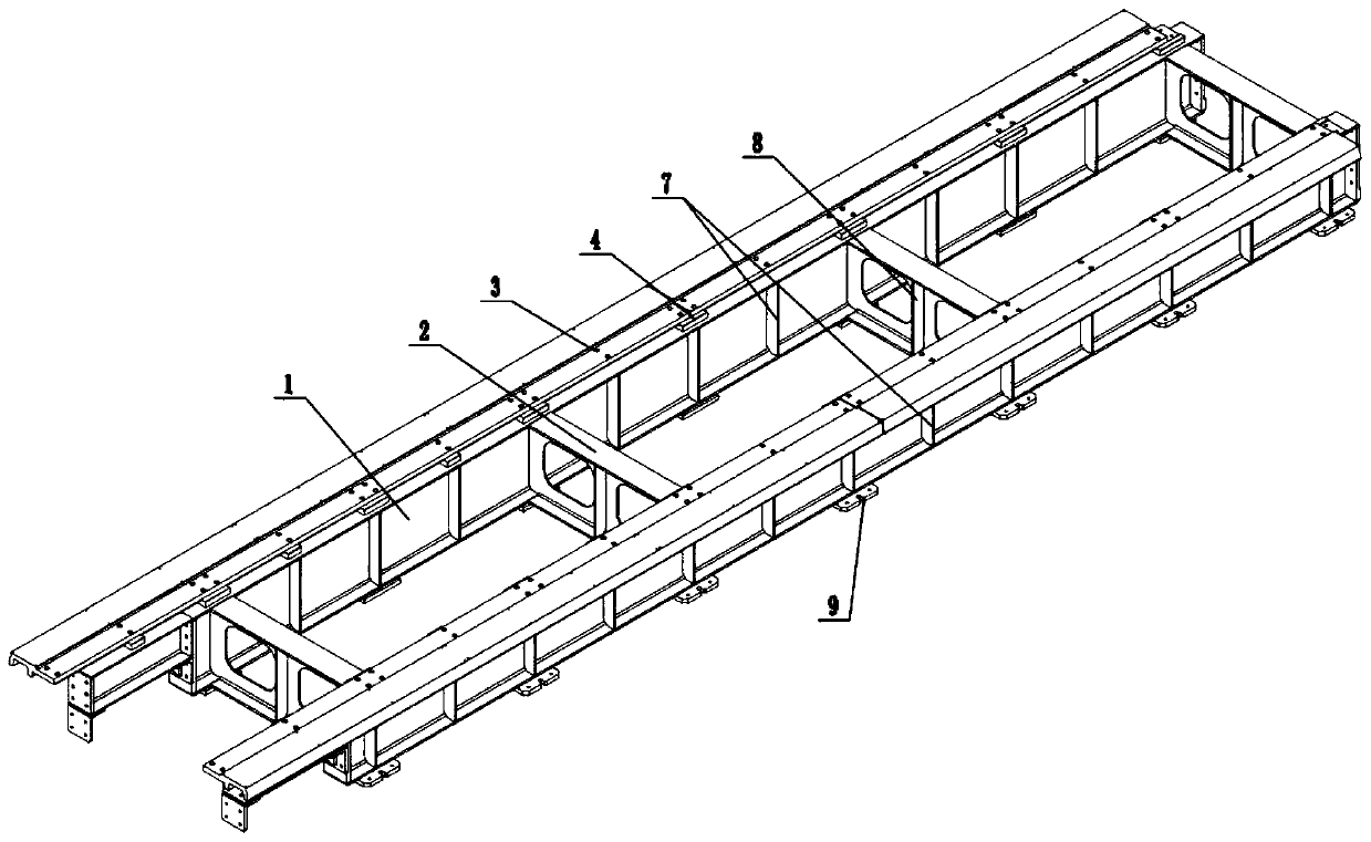
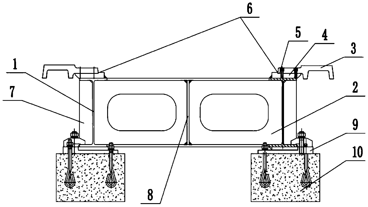
[0025] The present invention provides a modular F track beam, such as figure 1 , figure...


PUM


Abstract

The invention discloses a modularized F track beam. The track beam comprises a plurality of F track beam modules connected together. Each F track module comprises two main beams, a plurality of transverse beams and an F track arranged between the two main beams, wherein the two main beams are two pieces of H structural steel which are arranged longitudinally and are parallel to each other, the transverse beams are H structural steel, the tops of the two main beams are provided with a plurality of positioning blocks which are arranged longitudinally, the tops of the positioning blocks are provided with F track horizontal positioning faces and track gauge positioning faces perpendicular to the F track horizontal positioning faces, and the F track is positioned and installed through the F track horizontal positioning faces and the track gauge positioning faces; a plurality of main beam reinforcing ribs are arranged between bottom flanges and top flanges at the two sides of webs of the twomain beams; according to the modularized F track beam, the track beam rigidity is improved, additional vibration generated by insufficient rigidity of a circuit is avoided, and operation is stable; apositioning face is arranged between the track and the F track on the track beam, and rapid and accurate circuit installation and precision maintenance are facilitated.

Description

technical field [0001] The invention relates to the technical field of maglev train tracks, in particular to a modular F track beam. Background technique [0002] The maglev train is a rail vehicle that uses electromagnetic force to realize the non-contact support and guidance of the train, and realizes non-contact traction and braking through linear motors. The track used by medium and low-speed maglev trains is its unique F-shaped steel rail (also known as F rail). The maglev train is suspended by the electromagnet excitation installed on the train and below the F rail to generate suction force with the F rail. The suspension force is controlled by the suspension control system. The gap sensor in the suspension control system will feedback the measured gap between the electromagnet and the F rail and the vertical acceleration of the train to the suspension control system, so that it can generate a corresponding suspension force. At present, the requirement of the maglev t...

Claims


Application Information

Patent Timeline
Patent Type & Authority Applications(China)
IPC IPC(8): E01B25/30
CPCE01B25/305
Inventor 刘树洪张玉顺王连青
Owner TIANJIN GUANGSHAN JINDA MACHINERY
Learn More