
Laser marking equipment and focusing method thereof

A laser marking equipment and focusing technology, which is applied in the field of laser marking, can solve problems such as unspecified, hidden dangers, and inaccuracy, and achieve the effects of improving operational stability, wide application range, and improving accuracy

Active Publication Date: 2019-11-12
HANS LASER TECH IND GRP CO LTD
View PDF5 Cites 9 Cited by
  • Summary
  • Abstract
  • Description
  • Claims
  • Application Information

AI Technical Summary

Problems solved by technology

The disadvantages of this solution are: firstly, due to factors such as machining assembly error and hand wheel lubrication performance, it is desired to manually adjust the hand wheel 7 to make the adjustment error of the final focus position conform to the standard error range (within 0.1mm) It is difficult to realize, and at the same time, the problem of how to adjust the coordinates of the specific focus position on the marking plane 6 is not given in this scheme; further, after the adjustment of the focus height of the focus position is completed, if the hand During the locking process, due to pits, friction, gaps and other reasons, the specific focus position on the marking plane before and after the hand wheel is locked will deviate, resulting in the specific focus position after the hand wheel is locked. The change of marking effect caused by inaccuracy; if the handwheel is not locked, due to the machine vibration of the laser marking equipment and human error, the specific focus position may change without the operator's knowledge , will also bring changes in marking effects and even other hidden dangers

Method used


Image

  • Laser marking equipment and focusing method thereof
  • Laser marking equipment and focusing method thereof
  • Laser marking equipment and focusing method thereof

Examples


Embodiment Construction

[0051] In order to make the technical problems, technical solutions and beneficial effects to be solved by the present invention clearer, the present invention will be further described in detail below in conjunction with the accompanying drawings and embodiments. It should be understood that the specific embodiments described here are only used to explain the present invention, not to limit the present invention.

[0052] It should be noted that when an element is referred to as being “fixed” or “disposed on” another element, it may be directly on the other element or be indirectly on the other element. When an element is referred to as being "connected to" another element, it can be directly connected to the other element or indirectly connected to the other element.

[0053] It is to be understood that the terms "length", "width", "top", "bottom", "front", "rear", "left", "right", "vertical", "horizontal", "top" , "bottom", "inner", "outer" and other indicated orientations...


PUM


Abstract

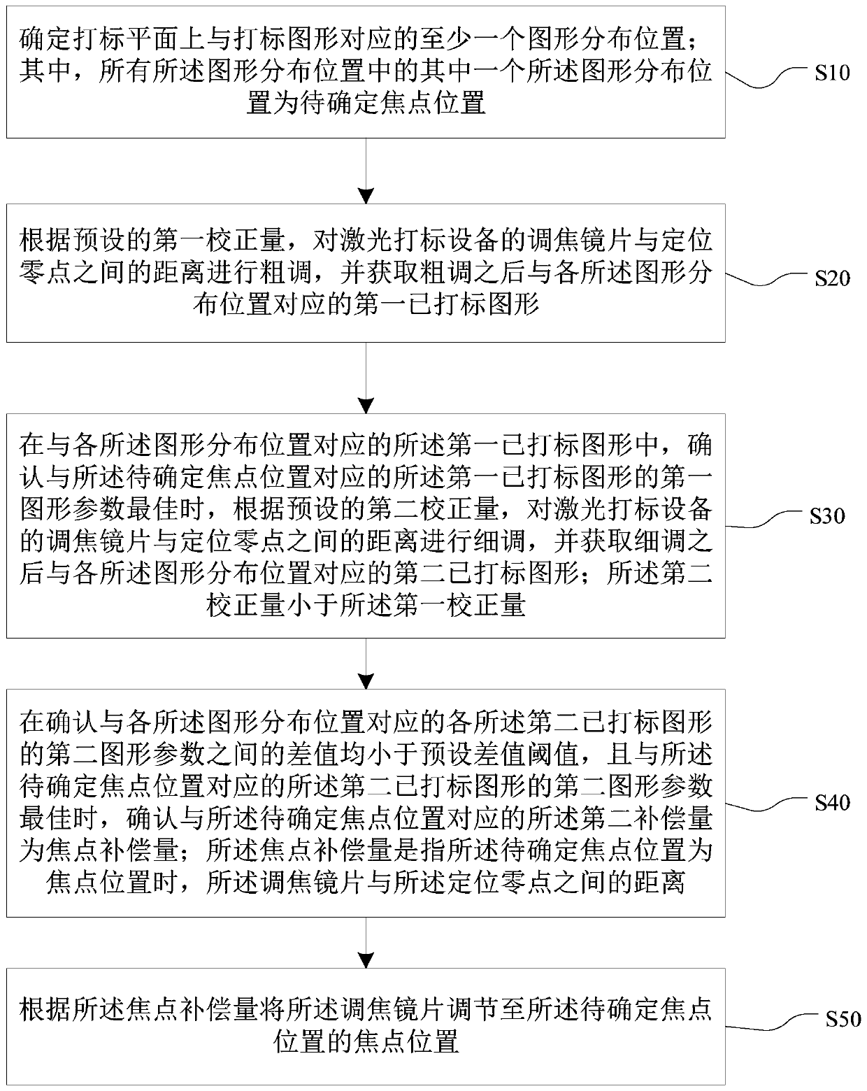
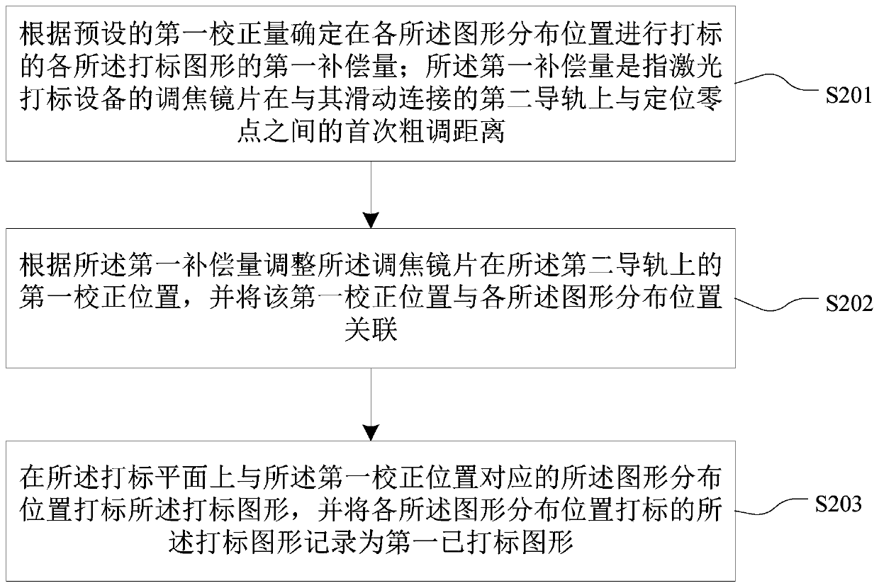
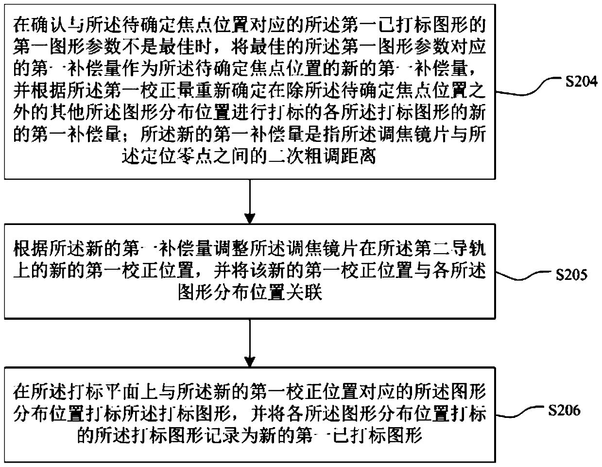
The invention provides laser marking equipment and a focusing method thereof. The method comprises the following steps of roughly adjusting the distance between a focusing lens and a positioning zeropoint according to a first correction amount and acquiring a first marked graph; finely adjusting the distance between the focusing lens and the positioning zero point according to a second correctingamount when confirming that a first graph parameter of the first marked graph corresponding to a to-be-determined focus position is optimal; determining a second compensation amount corresponding tothe to-be-determined focus position as a focus compensation amount when confirming that the difference value between second pattern parameters of each of second marked graphs corresponding to each ofpattern distribution positions is smaller than a preset difference value threshold value and the second graph parameters of the second marked graphs corresponding to the to-be-determined focus position is optimal; and adjusting the focusing lens to the focus point position of the to-be-determined focus position according to the focus compensation amount. According to the equipment and the method,the accuracy of determining the focus point of the laser marking equipment is greatly improved, the operation is simple and convenient, and the operation stability of equipment is improved.

Description

technical field [0001] The invention belongs to the technical field of laser marking, and more specifically relates to a focusing method for laser marking equipment. Background technique [0002] When the laser marking equipment respectively marks the marking positions A and B on the marking plane, due to the ideal laser focus, there is only one and the thinnest focus point (that is, the focal point), but between A and B When the points are marked separately, the focal length corresponding to the laser focus of the two marking positions will change. At this time, if the marking position is switched but the focus position does not change accordingly, the marking plane will not work at the optimal focus. , which will lead to thicker marking lines or poor marking effect. refer to Figure 8 After the laser beam emitted by the laser 1 in the laser marking device in the prior art passes through the focusing lens 21 and the focusing lens 3 in sequence, it is deflected by the galva...

Claims


Application Information

Patent Timeline
IPC IPC(8): B23K26/362B23K26/046
CPCB23K26/046B23K26/362
Inventor 陈略冯磊任宁高云峰
Owner HANS LASER TECH IND GRP CO LTD
Learn More