
Busbar capable of being quickly disassembled and assembled

A busbar, fast technology, applied to the parts of the connecting device, coupling device, output power conversion device, etc., can solve problems such as damage, device or power unit 3 wear, etc., to avoid repeated friction and reduce the damage rate. Effect

Active Publication Date: 2019-11-05
ZHUZHOU CSR TIMES ELECTRIC CO LTD
View PDF5 Cites 0 Cited by
  • Summary
  • Abstract
  • Description
  • Claims
  • Application Information

AI Technical Summary

Problems solved by technology

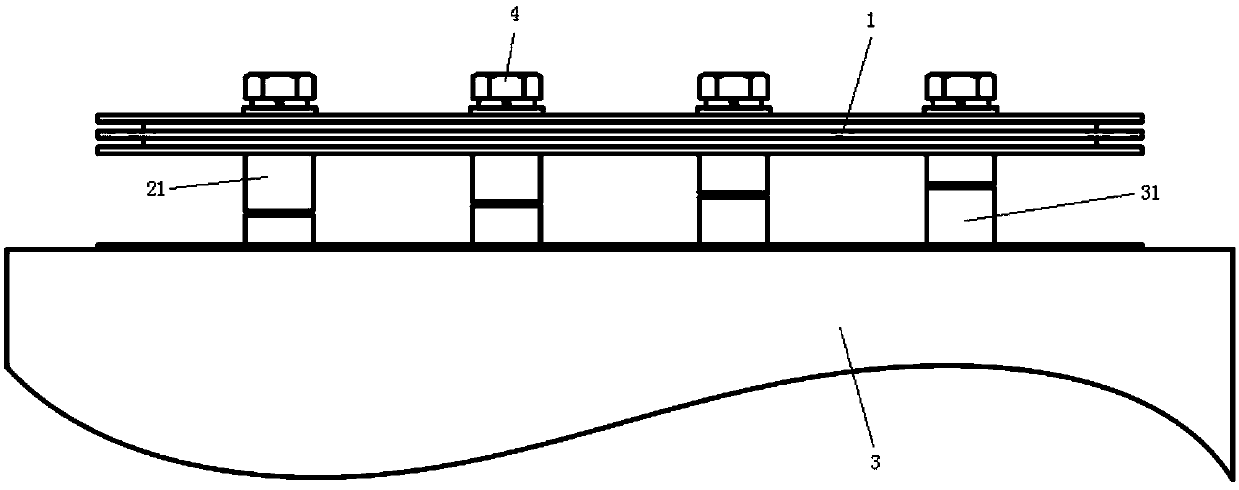
[0003] However, there are also the following disadvantages: multiple devices or multiple power units are connected in parallel on the busbar 1, since the target device or power unit is electrically connected through the conductive column 13 on the busbar 1, if it needs to be replaced or removed When one of the devices or a power unit 3 is used, all the connecting bolts corresponding to the target device or power unit on the busbar need to be removed before the device or power unit can be pulled out from the busbar. However, since the existing busbar is divided into Busbars without conductive columns (such as image 3 shown) and busbars with conductive posts (such as Figure 5 shown), and the height of the conductive pillars 13 on the busbar with conductive pillars is equal, so that when the device or power unit 3 is pulled out, the upper surface of the device or power unit 3 will be sequentially connected to the passing multiple conductive pillars 13 are in contact and generate multiple frictions (such as Figure 4 and Image 6 shown), so it will cause wear and damage to busbars, devices or power unit 3

Method used


Image

  • Busbar capable of being quickly disassembled and assembled
  • Busbar capable of being quickly disassembled and assembled
  • Busbar capable of being quickly disassembled and assembled

Examples


Embodiment Construction

[0022] The present invention will be further described below in conjunction with accompanying drawing. In this way, the realization process of how the present invention uses technical means to solve technical problems and achieve technical effects can be fully understood and implemented accordingly. It should be noted that, as long as there is no conflict, the technical features mentioned in the various embodiments can be combined in any manner. The present invention is not limited to the specific embodiments disclosed herein, but includes all technical solutions falling within the scope of the claims.

[0023] It should be noted in the present invention that the term "row" used in the present invention is used to define that the connection structure is arranged along the horizontal direction of the busbar.

[0024] The busbar 1 of the present invention can be quickly disassembled and assembled with the power unit 3, such as figure 1 As shown, it is a front view of the stru...


PUM


Abstract

The invention relates to a busbar capable of being quickly disassembled and assembled. A plurality of rows of parallel connection structures are arranged on the lower surface of the busbar. Each row of connection structures is composed of a plurality of first conductive seats. Two ends of each row of connection structures are defined as an inlet end and a stop end respectively, wherein the heightof the first conductive seat in each row of connection structures is gradually reduced from the stop end to the inlet end. By means of the busbar, a device or a power unit can be quickly disassembledor connected to the busbar, and damage caused by repeated friction between the busbar and the device or the power unit can be avoided.

Description

technical field [0001] The invention belongs to the technical field of power electronics, and in particular relates to a busbar capable of quick assembly and disassembly. Background technique [0002] In the engineering design of medium and large-capacity IGBT inverters, it is very important to arrange busbars reasonably and reduce distributed inductance to protect IGBT components from transient overvoltage breakdown. Therefore, it is necessary to seek structural design and The fabrication method has become one of the key technologies in the main circuit design of the IGBT inverter. Although the existing various low-inductance busbars can meet the basic requirements of the main circuit structure design of the IGBT inverter. [0003] However, there are also the following disadvantages: multiple devices or multiple power units are connected in parallel on the busbar 1, since the target device or power unit is electrically connected through the conductive column 13 on the busb...

Claims


Application Information

Patent Timeline
Patent Type & Authority Applications(China)
IPC IPC(8): H02M7/00H01R13/506
CPCH01R13/506H02M7/003
Inventor 史虎胡家喜王婷李滔李勇孙胜苗郭世慧黄华坤
Owner ZHUZHOU CSR TIMES ELECTRIC CO LTD
Learn More