Drying device for furniture production
A drying device and furniture technology, applied in the direction of drying, drying machine, drying gas arrangement, etc., can solve the problems of time-consuming and laborious, unfavorable production, low work efficiency, etc., achieve wide application range, reduce contact surface, and facilitate clamping effect
- Summary
- Abstract
- Description
- Claims
- Application Information
AI Technical Summary
Problems solved by technology
Method used
Image
Examples
Embodiment 1
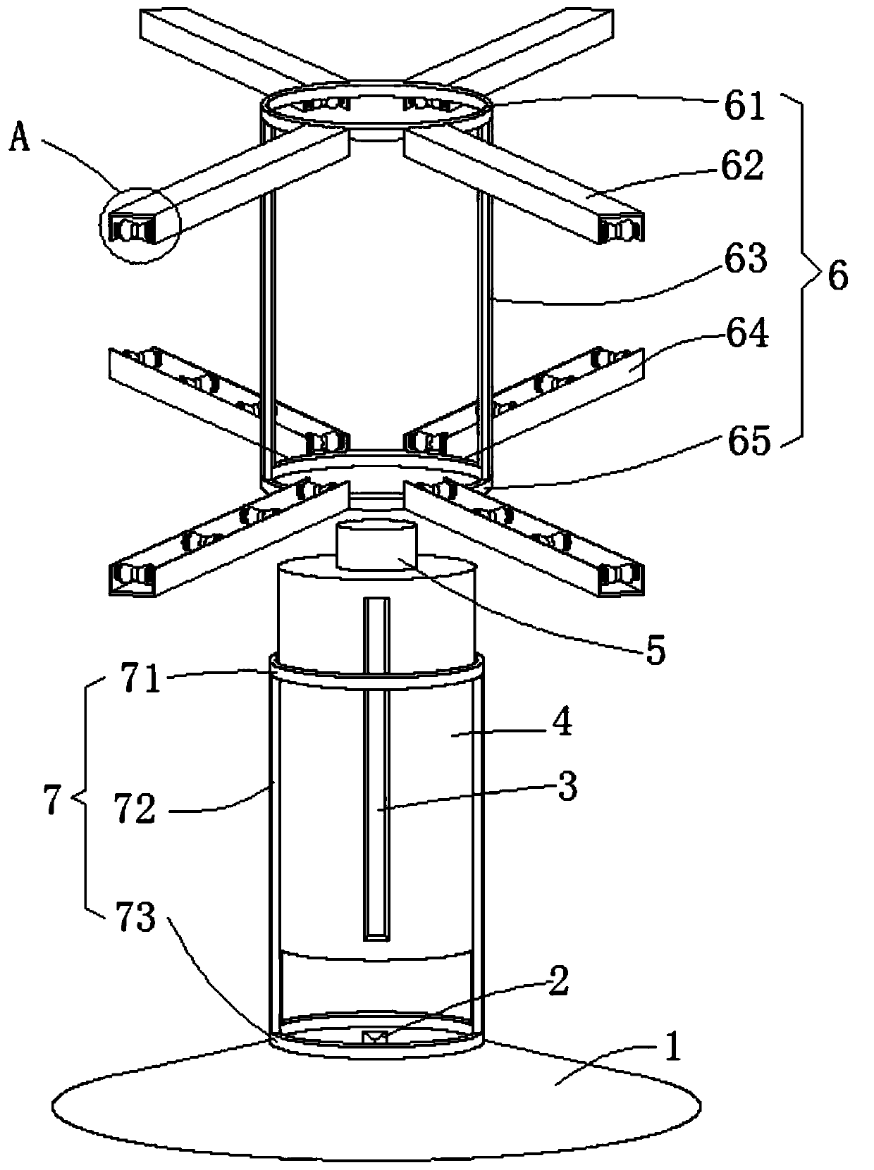
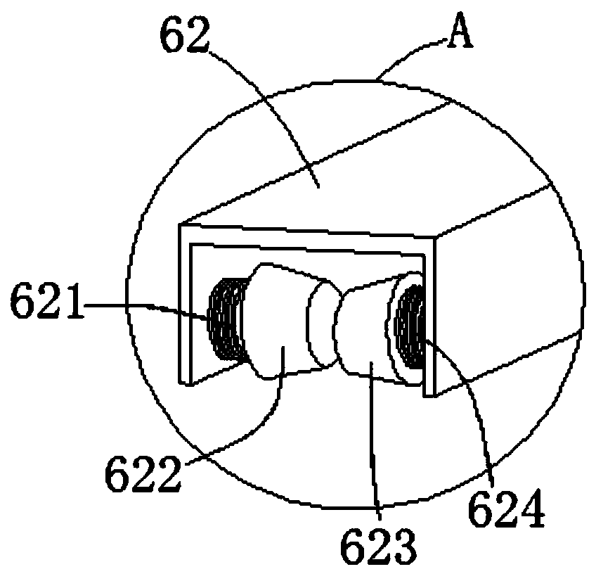
[0025] see Figure 1-3 , this embodiment provides a drying device for furniture production, including a base 1, a support frame 7 and a fixed frame 6, a rotating motor 8 is provided in the center of the inner cavity of the base 1, and the rotating motor 8 runs through the base 1 through a power shaft. The top end surface is connected with the auxiliary rotating shaft 2. The support frame 7 includes a first annular support frame 71, a second annular support frame 73 and two first support columns 72. The support frame 7 is fixedly welded by the second annular support frame 73. On the top surface of the base 1 , between the inner chambers of the first annular support frame 71 and the second annular support frame 73 , a blower tube 4 is slid and plugged vertically, and the lower end of the blower tube 4 is connected to the auxiliary rotating shaft 2 , the fixed frame 6 includes a first annular fixed frame 61, a second annular fixed frame 65 and two second support columns 63, the o...
Embodiment 2
[0033] see Figure 1-3 , further improvements have been made on the basis of Example 1:
[0034] The base 1 has a truncated cone structure, and the inner cavity is a hollow structure, which is convenient for installing and placing the rotating motor 8 .
[0035]The outer diameters of the first annular support frame 71 and the second annular support frame 73 are the same, the outer diameters of the first annular fixed frame 61 and the second annular fixed frame 65 are the same, and are the first annular support frame 71 and the second annular support frame 73 1.2 times the outer diameter, so that the support frame 7 can be slidably sleeved on the outer wall of the fixed frame 6, and can be disassembled to facilitate splicing and assembly.
[0036] The left and right sides between the first annular fixed frame 61 and the second annular fixed frame 65 are respectively fixed and welded by two second support columns 63, and the length of the second support columns 63 is the same a...
PUM
 Abstract
Description
Claims
Application Information
 - R&D Engineer
- R&D Manager
- IP Professional
- Industry Leading Data Capabilities
- Powerful AI technology
- Patent DNA Extraction
Browse by: Latest US Patents, China's latest patents, Technical Efficacy Thesaurus, Application Domain, Technology Topic, Popular Technical Reports.
© 2024 PatSnap. All rights reserved.Legal|Privacy policy|Modern Slavery Act Transparency Statement|Sitemap|About US| Contact US: help@patsnap.com


