
Deep-well pump transmission shaft system

A transmission shaft and deep well pump technology, applied in the direction of pumps, pump control, pump devices, etc., can solve the problems of limited transmission distance and inability to meet the long-distance power transmission of product oil tankers

Active Publication Date: 2019-11-05
WUHAN MARINE MACHINERY PLANT
View PDF5 Cites 0 Cited by
  • Summary
  • Abstract
  • Description
  • Claims
  • Application Information

AI Technical Summary

Problems solved by technology

[0004] However, the existing long-axis power transmission equipment of common deep well pumps uses the long axis for direct transmission, and the direct transmission of the long axis will make the transmission distance limited, so that it cannot meet the long-distance power transmission for product oil tankers and chemical tankers.

Method used


Image

  • Deep-well pump transmission shaft system
  • Deep-well pump transmission shaft system
  • Deep-well pump transmission shaft system

Examples


Embodiment Construction

[0025] In order to make the object, technical solution and advantages of the present invention clearer, the implementation manner of the present invention will be further described in detail below in conjunction with the accompanying drawings.

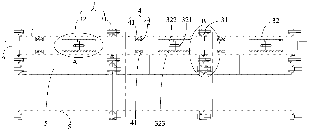
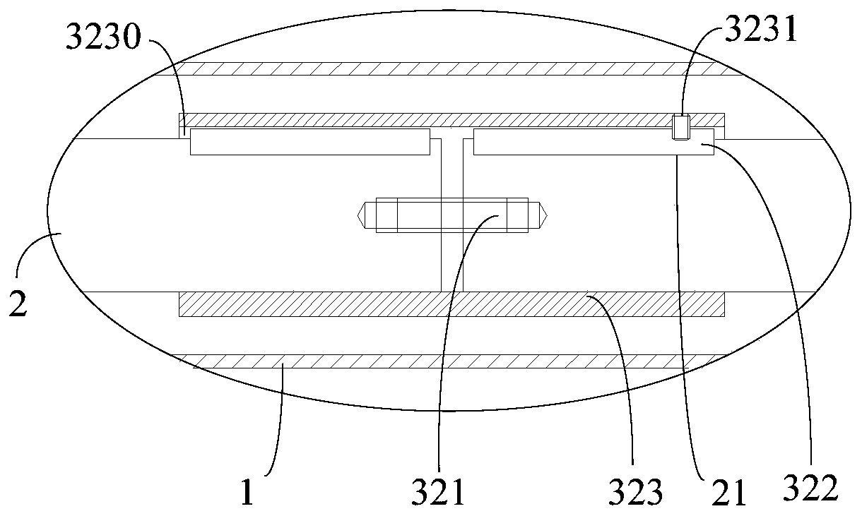
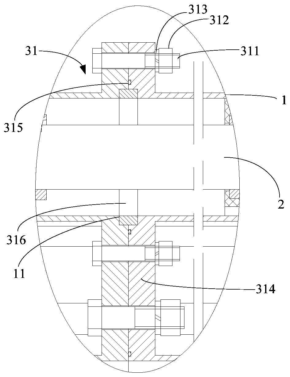
[0026] The embodiment of the present invention provides a deep well pump drive shaft system, such as figure 1 As shown, the transmission shaft system of the deep well pump includes a pipe string 1, a transmission shaft 2, and a connecting mechanism 3. The transmission shaft 2 is installed inside the pipe string 1, and the connecting mechanism 3 includes a first connecting assembly 31 and a second connecting assembly 32. A connection assembly 31 is used to connect the end surfaces of two adjacent pipe strings 1 together, and a second connection assembly 32 is used to connect the end surfaces of two adjacent transmission shafts 2 together. The second connection assembly 32 includes a mounting part 321 , the clamping piece 322 and the sha...


PUM


Abstract

The invention discloses a deep-well pump transmission shaft system. The deep-well pump transmission shaft system involves pipe columns, transmission shafts and a connecting mechanism, wherein the transmission shafts are arranged in the pipe columns; the connecting mechanism comprises first connecting assemblies and second connecting assemblies, wherein the first connecting assemblies are used forconnecting the end surfaces of the two adjacent pipe columns together, and the second connecting assemblies are used for connecting the end surfaces of the two adjacent transmission shafts together; and the second connecting assemblies comprise mounting pieces, clamping pieces and couplings, for all the second connecting assemblies, the two ends of the mounting pieces are arranged on the two adjacent transmission shafts in the axial directions of the transmission shafts, the couplings are arranged on joints between the two adjacent transmission shafts in a sleeving manner, the clamping piecesare arranged on the outer circumferential walls of the transmission shafts in the axial directions of the transmission shafts, and the clamping pieces are clamped between the couplings and the transmission shafts. According to the shaft system, the pipe columns serve as supporting bodies of the transmission shafts, the power is transmitted through the transmission shafts, the sectional type connecting form of the pipe columns and the transmission shafts is adopted, and the requirement for long-distance driving of a deep-well pump is finally met.

Description

technical field [0001] The invention relates to the field of deep well pumps, in particular to a deep well pump drive shaft system. Background technique [0002] A deep well pump is a device used to pump liquid cargo from the liquid cargo tank to the outside of the liquid cargo tank. Common deep well pumps usually include a pump body placed in the liquid cargo tank, a motor placed outside the liquid cargo tank, and a drive shaft set between the pump body and the motor. The drive shaft system is used to transmit the power output by the motor to pump body. [0003] Most of the existing deep well pump long-axis power transmission equipment is a vertical single-suction multi-stage centrifugal pump. The impeller is installed below the dynamic water level in the well, and the power machine is installed on the well. The impeller is driven to rotate in the diversion shell through the long-axis transmission. The water flows along the flow channel between the diversion shell and the...

Claims


Application Information

Patent Timeline
IPC IPC(8): F04D13/02F04D13/10F04D29/62F04D29/044F04D29/06F04D27/00
CPCF04D13/021F04D13/10F04D27/001F04D29/044F04D29/061F04D29/628
Inventor 白俊江王坚赵雷刚
Owner WUHAN MARINE MACHINERY PLANT
Learn More