
A calibration device for high-precision auto parts

A technology for auto parts and calibration devices, which is applied to measurement devices, optical devices, instruments, etc., can solve the problems of low detection accuracy, low efficiency, poor work efficiency, etc., and achieve the effect of improving calibration efficiency and accuracy.

Active Publication Date: 2021-01-29
安徽东鸥机械科技有限公司
View PDF8 Cites 0 Cited by
  • Summary
  • Abstract
  • Description
  • Claims
  • Application Information

AI Technical Summary

Problems solved by technology

[0002] In the process of vehicle parts processing, for example, some mounting plates, wind deflectors or brackets, main boards and other components need to be processed with punching holes. After the punching holes are processed, the position of the punching holes needs to be detected to prevent the punching holes from being missed; Traditional punching hole detection is mostly manual detection. If the number of punching holes on the processed plate is small, manual detection is more convenient, but if the number of punching holes is large, or even hundreds, manual detection needs to compare drawings, and can only Single wells are detected one by one, resulting in low detection accuracy and poor work efficiency
[0003] To sum up, in the proofreading process of existing auto parts, manual inspection plays an important role in the production and processing of auto parts, but at the same time, this inspection method has low efficiency, high labor costs, and Disadvantages of being prone to detection errors

Method used


Image

  • A calibration device for high-precision auto parts
  • A calibration device for high-precision auto parts
  • A calibration device for high-precision auto parts

Examples


Embodiment Construction

[0025] The following will clearly and completely describe the technical solutions in the embodiments of the present invention with reference to the accompanying drawings in the embodiments of the present invention. Obviously, the described embodiments are only some, not all, embodiments of the present invention.

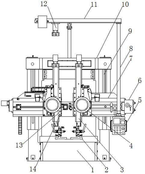
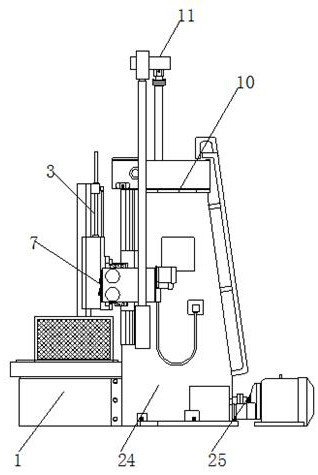
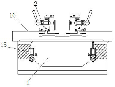
[0026] refer to Figure 1-5 , a proofreading device for high-precision auto parts, comprising a cabinet body 24, a base drive motor 25 is fixed on one side of the cabinet body 24 by bolts, and the output shaft of the base drive motor 25 is connected with a drive screw, which drives The outer wall of the lead screw is connected with the base 1 through threads, and the two ends of the outer wall of the side of the cabinet 24 close to the base 1 are fixed with longitudinal slide rails 9 by bolts, and the inner wall of the longitudinal slide rail 9 is slidably connected with a horizontal mobile frame 7 , the outer wall of the opposite side of the horizontal moving frame ...


PUM


Abstract

The invention belongs to the technical field of automobile production equipment, in particular to a calibration device for high-precision auto parts. Aiming at the problems of low efficiency of manual calibration and high detection error, the following scheme is proposed, including a cabinet, one of which is The base driving motor is fixed on the side outer wall through bolts, and the output shaft of the base driving motor is connected with a driving screw, and the outer wall of the driving screw is connected with the base through threads. The present invention realizes X, Y and Z multi-directional adjustments through longitudinal slide rails, horizontal moving frames, moving arms and detection adsorption plates, hydraulic struts and base drive motors are adjusted up and down and front and rear, and upper slides and high-definition detection probes Cooperate with the movement to realize the calibration of the multi-angle overall outer surface of the auto parts fixed on the fixture, improve the efficiency of parts calibration, insert the positioning signal device and fix it on the positioning board, and can be freely combined to realize the positioning of the punching positions of different parts And proofreading, to ensure that the punching and proofreading position is more accurate.

Description

technical field [0001] The invention relates to the technical field of automobile production equipment, in particular to a proofreading device for high-precision automobile parts. Background technique [0002] In the process of vehicle parts processing, for example, some mounting plates, wind deflectors or brackets, main boards and other components need to be processed with punching holes. After the punching holes are processed, the position of the punching holes needs to be detected to prevent the punching holes from being missed; Traditional punching hole detection is mostly manual detection. If the number of punching holes on the processed plate is small, manual detection is more convenient, but if the number of punching holes is large, or even hundreds, manual detection needs to compare drawings, and can only Single wells are detected one by one, resulting in low detection accuracy and poor work efficiency. [0003] To sum up, in the proofreading process of existing aut...

Claims


Application Information

Patent Timeline
Patent Type & Authority Patents(China)
IPC IPC(8): G01B11/00G01B11/12
CPCG01B11/00G01B11/12
Inventor 邱智伟
Owner 安徽东鸥机械科技有限公司
Learn More