
Shift management in model predictive based propulsion system control

A propulsion system and control system technology, applied in the direction of control devices, external condition input parameters, driver input parameters, etc.

Active Publication Date: 2019-10-25
GM GLOBAL TECH OPERATIONS LLC
View PDF18 Cites 2 Cited by
  • Summary
  • Abstract
  • Description
  • Claims
  • Application Information

AI Technical Summary

Problems solved by technology

However, in some cases other shift patterns or pulley ratios may be desirable

Method used


Image

  • Shift management in model predictive based propulsion system control
  • Shift management in model predictive based propulsion system control
  • Shift management in model predictive based propulsion system control

Examples


Embodiment Construction

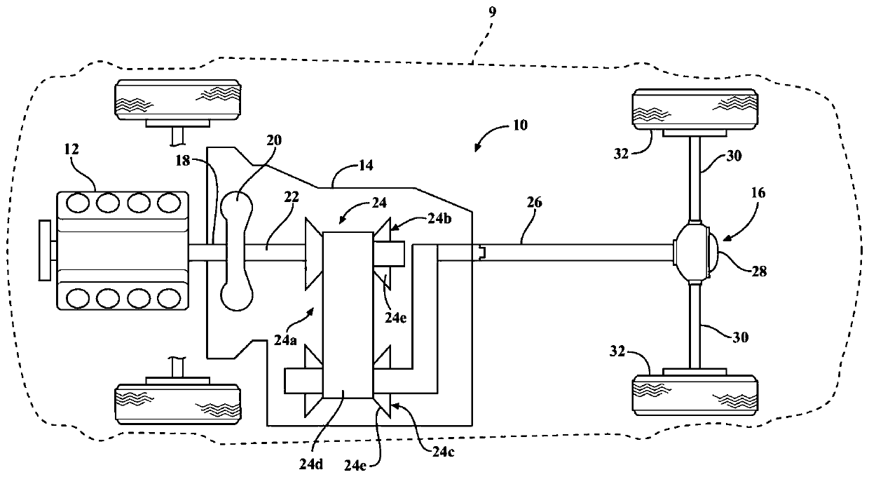
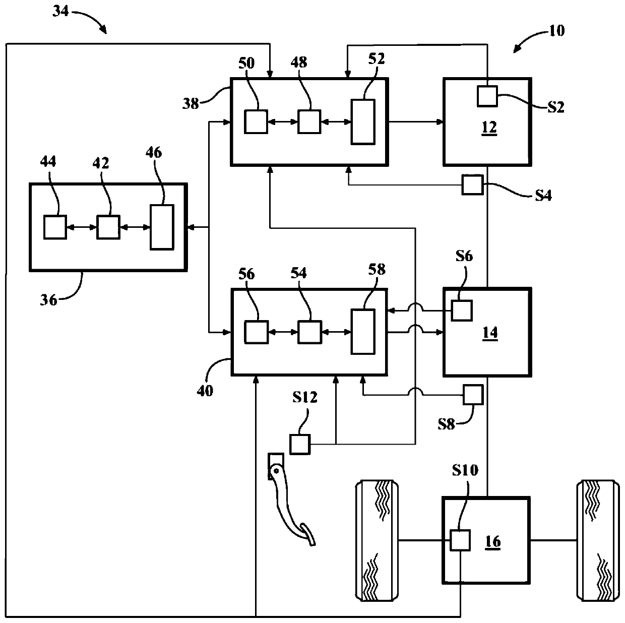
[0064] refer to figure 1 , shows an exemplary motor vehicle and is generally indicated by reference numeral 9 . Motor vehicle 9 is illustrated as a passenger car, but it should be understood that motor vehicle 9 may be any type of vehicle, such as a truck, van, sport utility vehicle, or the like. Motor vehicle 9 includes an exemplary propulsion system 10 . It should be understood at the outset that while a rear-wheel drive propulsion system 10 has been illustrated, the motor vehicle 9 may have a front-wheel drive propulsion system, an all-wheel drive propulsion system, or four-wheel drive propulsion systems without departing from the spirit and scope of the present disclosure. drive propulsion system.

[0065] Propulsion system 10 generally includes an engine 12 interconnected with a transmission 14 and a final drive unit 16 . Engine 12 may be a conventional internal combustion or electric motor, a hybrid engine, or any other type of prime mover without departing from the s...


PUM


Abstract

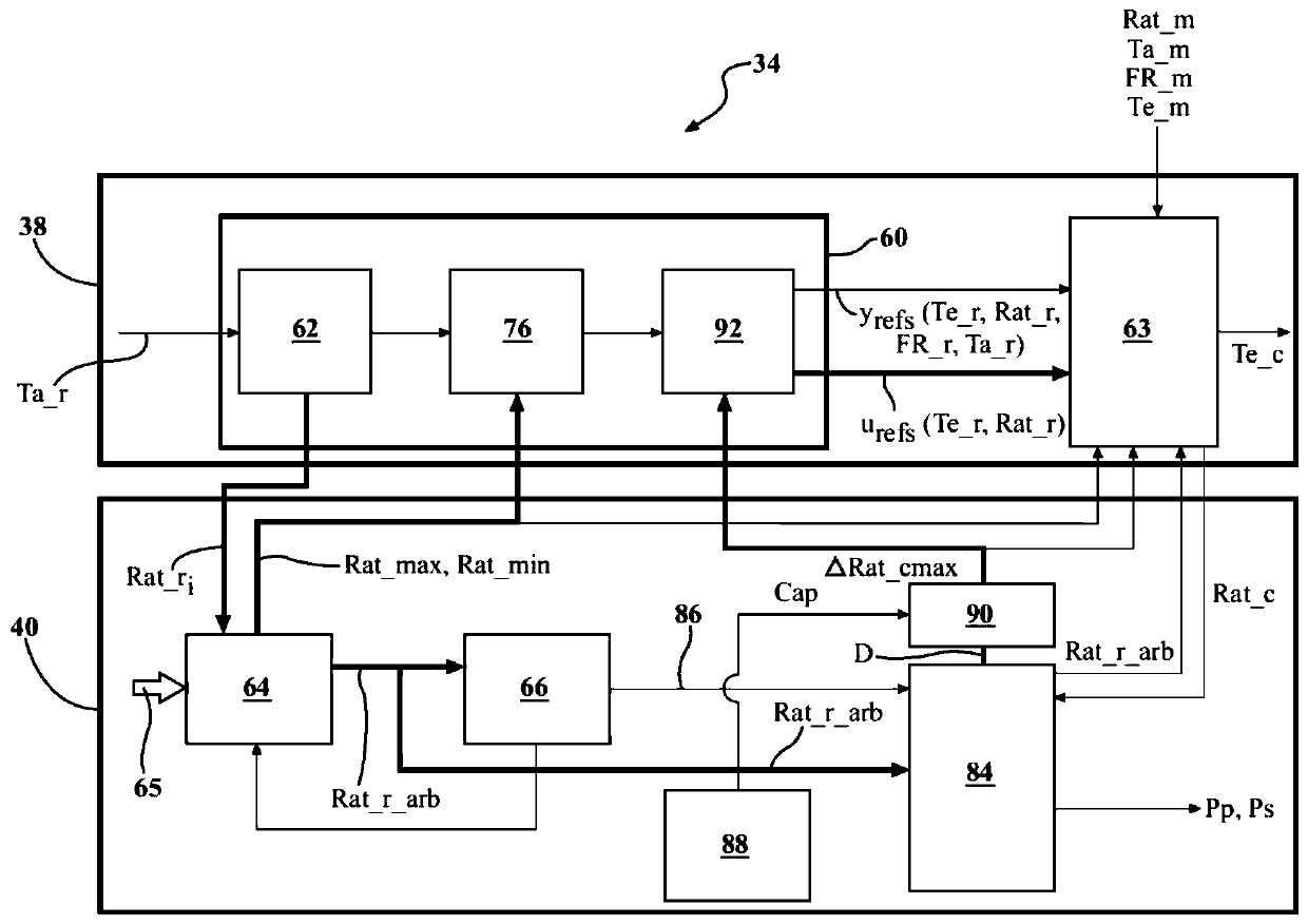
A propulsion system, control system, and method use model predictive control systems to generate a plurality of sets of possible command values and determine a cost for each set of possible command values. The set of possible command values that has the lowest cost is determined and defined as a selected set of command values. In some circumstances, the MPC-determined command value may be replacedby another transmission ratio command based on override inputs. Minimum and maximum transmission ratios are determined based on the override inputs, and a constrained (or arbitrated) transmission ratio is determined therefrom. The constrained or arbitrated transmission ratio is used to determine whether to apply an MPC-determined transmission ratio or a transmission ratio based on the arbitratedtransmission ratio to determine an ultimate commanded transmission ratio. Pressure(s) are commanded to a transmission pulley assembly, which is configured to implement the ultimate commanded transmission ratio.

Description

technical field [0001] The present disclosure relates to a control system and method for a propulsion system of a motor vehicle having an engine and a transmission, and more particularly to a control system and method using a multivariable controller. Background technique [0002] Propulsion system control in a motor vehicle typically involves reading driver and vehicle inputs, such as accelerator pedal position, vehicle sensor data, and torque requests, and communicating these inputs to the engine control module (ECM) and transmission control module ( TCM). The ECM can calculate the requested axle torque from driver and vehicle inputs. The requested axle torque may then be communicated to the engine and ECM. The engine is controlled to produce actual axle torque based on the requested axle torque. At the same time, and typically simultaneously with the calculation of desired engine and axle torques, the desired gear ratio is calculated from the requested axle torque and ...

Claims


Application Information

Patent Timeline
IPC IPC(8): B60W30/18B60W10/06B60W10/10
CPCB60W30/18B60W10/06B60W10/10B60W2710/0666B60W2710/1005B60W10/04B60W50/06B60W50/10B60W2710/10B60W30/188B60W2710/1083B60W10/107B60W30/18136B60W30/18072B60W2510/0657B60W2510/0676B60W2510/069B60W2510/101B60W2510/107B60W2510/0623B60W2540/16B60W2520/30B60W2520/40B60W2555/40
Inventor P·G·奥塔内斯M·李维斯兹C·J·温格兹C·莱因霍尔德M·T·萨兹姆斯基M·M·诺瓦克B·帕提帕提
Owner GM GLOBAL TECH OPERATIONS LLC
Learn More