Surgical robot and surgical instrument
A technique for surgical instruments and instruments, applied in the field of surgical robots and surgical instruments, can solve problems such as cross-wear of steel wires
- Summary
- Abstract
- Description
- Claims
- Application Information
AI Technical Summary
Problems solved by technology
Method used
Image

Examples
Embodiment 1
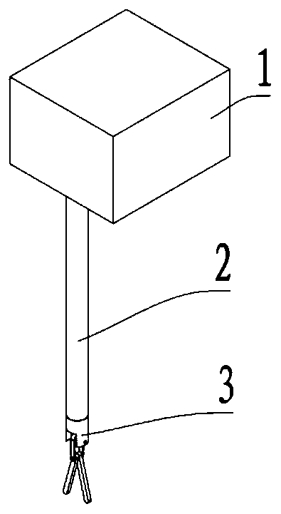
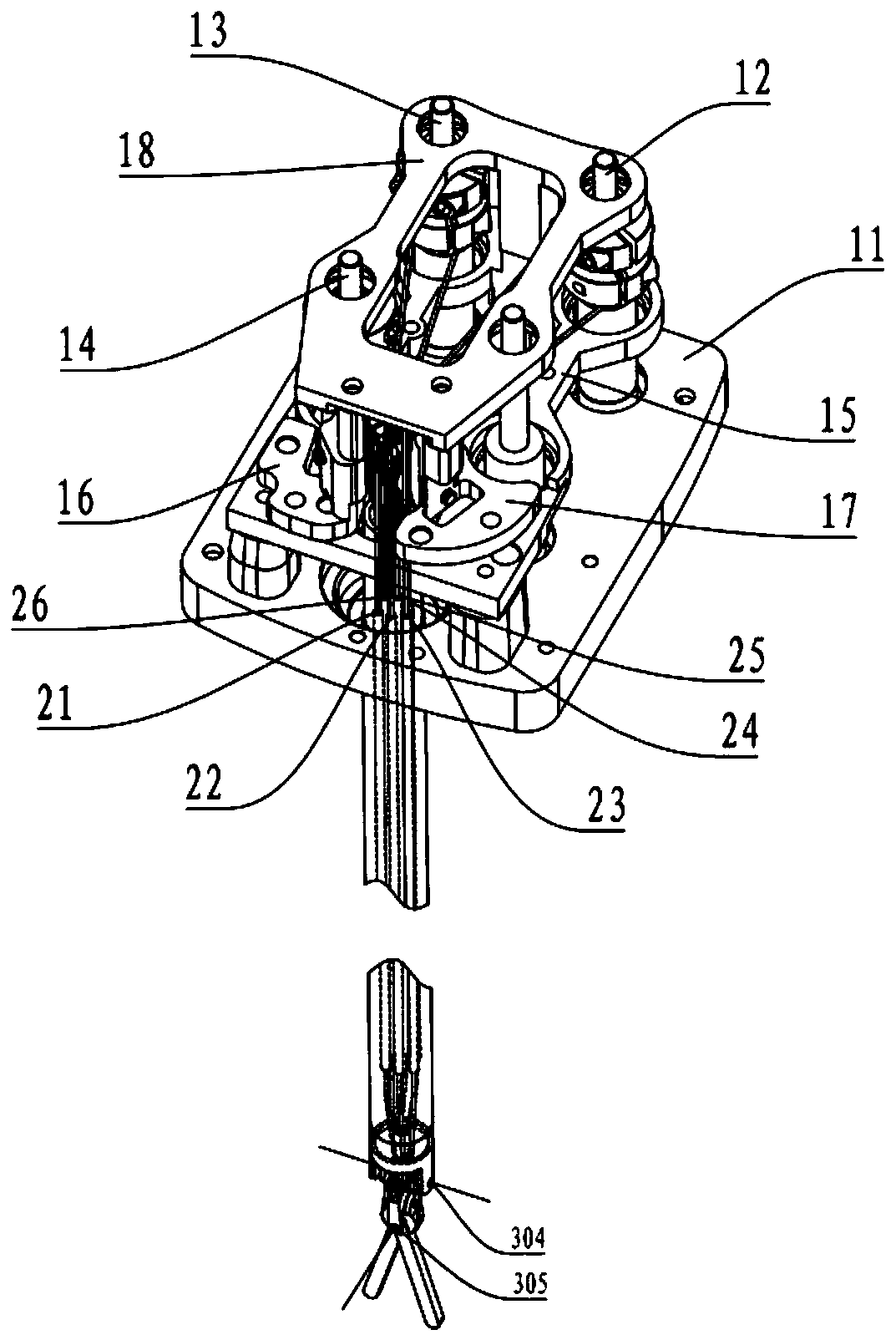
[0108] Please refer to Figure 1 to Figure 13 and Figure 27 ,in, figure 1 It is a schematic diagram of the overall structure of the surgical instrument provided by Embodiment 1 of the present invention, figure 2 It is a schematic diagram of the internal structure of the surgical instrument provided by Embodiment 1 of the present invention, image 3 It is a schematic diagram of the wire transmission structure provided by Embodiment 1 of the present invention, Figure 4 It is a schematic diagram of the guide seat provided by Embodiment 1 of the present invention, Figure 5 is a schematic diagram of the first transmission module provided in Embodiment 1 of the present invention, Image 6 It is a schematic diagram of the second transmission module provided by Embodiment 1 of the present invention, Figure 7 is a schematic diagram of the third transmission module provided by Embodiment 1 of the present invention, Figure 8 It is a schematic diagram of the transmission plane...
Embodiment 2
[0143] The surgical instrument in the second embodiment of the present invention is basically the same as the surgical instrument in the first embodiment, the same parts will not be described, and only the differences will be described below.
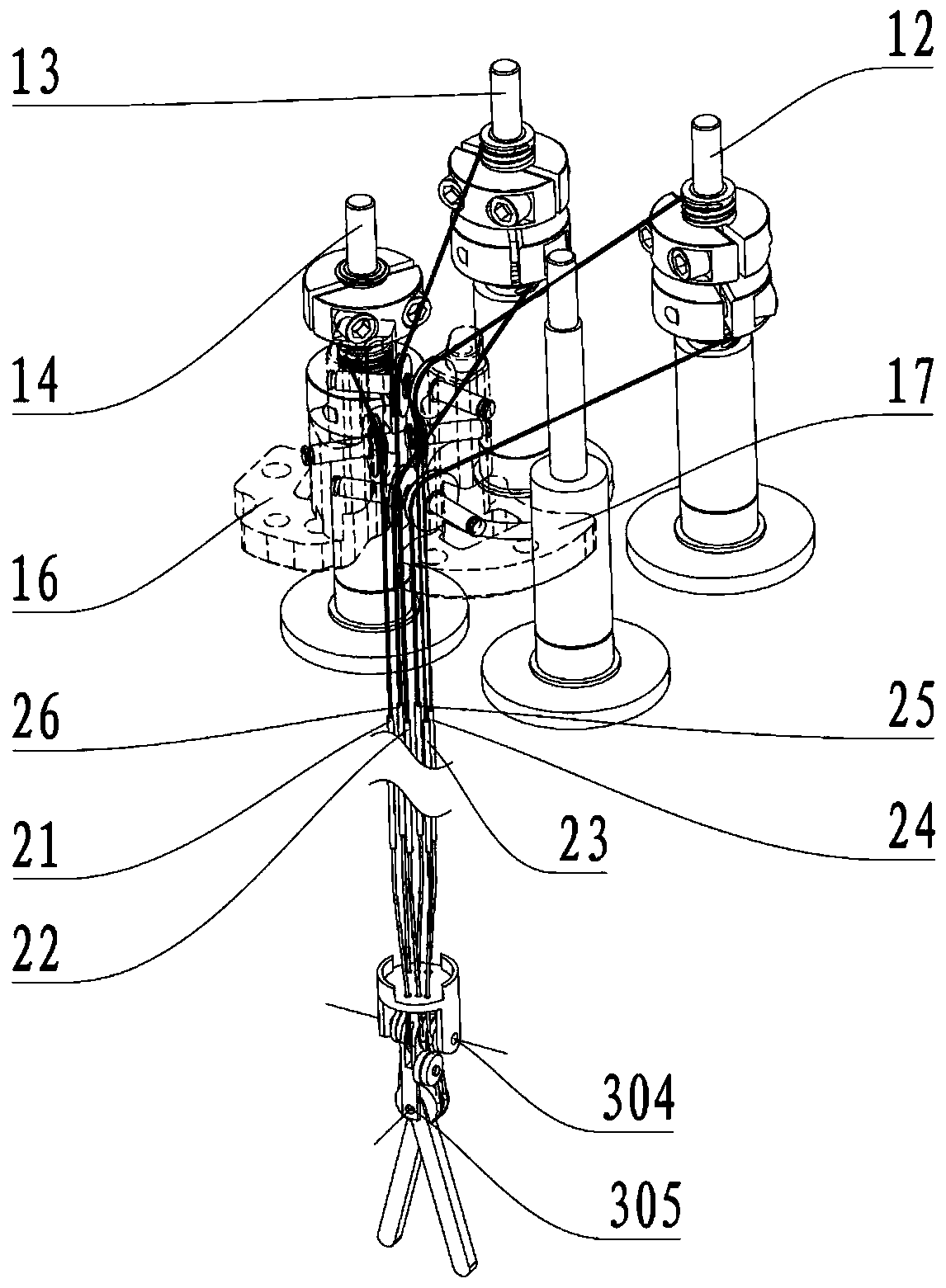
[0144] Please refer to Figure 14 and Figure 15 ,in Figure 14 It is a top view of the wire transmission structure provided by Embodiment 2 of the present invention, Figure 15 It is a perspective view of the wire transmission structure provided by Embodiment 2 of the present invention.
[0145] In the second embodiment, the arrangement of the guide wheels corresponding to the traction body on the guide seat is different from that in the first embodiment. Specifically, such as Figure 14 to Figure 15 As shown, the first guide seat 17 is provided with the third guide wheel 161, the first guide wheel 171 and the sixth guide wheel 173; the second guide seat 16 is provided with the fifth guide wheel 163, the second guide wheel 175 and ...
Embodiment 3
[0148] The surgical instrument in the third embodiment of the present invention is basically the same as the surgical instrument in the first embodiment, the same parts will not be described, and only the differences will be described below.
[0149] Please refer to Figure 16 , which is a schematic diagram of the transmission plane of the wire transmission structure provided by Embodiment 3 of the present invention.
[0150] In the third embodiment, the arrangement of the end drive shafts corresponding to the traction body is different from that in the first embodiment. Specifically, such as Figure 16 As shown, the third end drive shaft 14 of the third transmission module is farther away from the end of the instrument than the second end drive shaft 13 of the second transmission module. Further, the first end drive shaft 12 of the first transmission module and the third end drive shaft 14 of the third transmission module are arranged symmetrically with respect to the secon...
PUM
 Abstract
Description
Claims
Application Information
 - R&D
- Intellectual Property
- Life Sciences
- Materials
- Tech Scout
- Unparalleled Data Quality
- Higher Quality Content
- 60% Fewer Hallucinations
Browse by: Latest US Patents, China's latest patents, Technical Efficacy Thesaurus, Application Domain, Technology Topic, Popular Technical Reports.
© 2025 PatSnap. All rights reserved.Legal|Privacy policy|Modern Slavery Act Transparency Statement|Sitemap|About US| Contact US: help@patsnap.com