
Aircraft cabin data distribution method and system

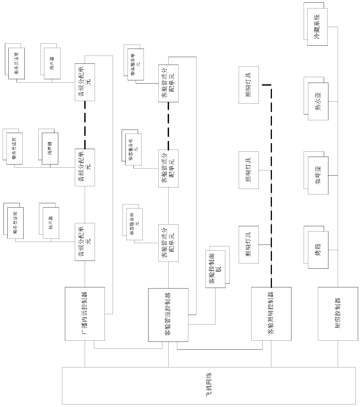
A data distribution and cabin technology, applied in the field of aircraft systems, can solve the problems of low integration, complex data system configuration, low flexibility and scalability, etc.

Inactive Publication Date: 2019-10-18
COMAC +1
View PDF4 Cites 3 Cited by
  • Summary
  • Abstract
  • Description
  • Claims
  • Application Information

AI Technical Summary

Problems solved by technology

[0004] Since the data distribution network deployed for each head-end controller is independent of each other and may use different interfaces and communication protocols, each head-end controller is also separately connected to the aircraft network, which makes a large number of network nodes and interfaces repeatedly deployed, and the entire data system structure complex type, low integration
In addition, when the cabin layout changes, all data distribution networks must be changed accordingly, which is not very flexible and scalable

Method used


Image

  • Aircraft cabin data distribution method and system
  • Aircraft cabin data distribution method and system
  • Aircraft cabin data distribution method and system

Examples


example 1

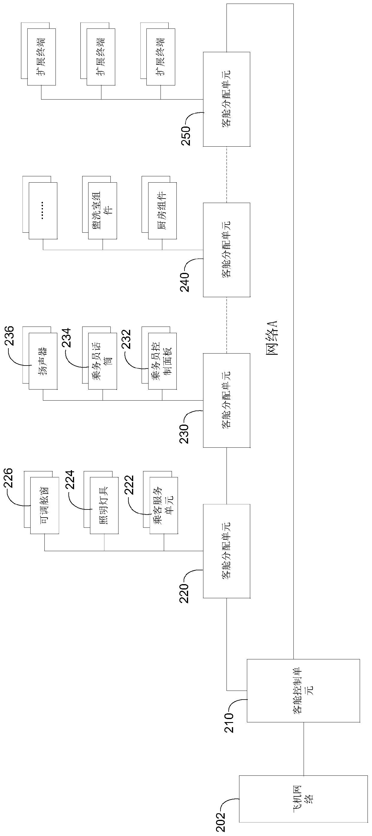
[0070] Example 1: Assume that the flight attendant microphone 234 and speaker 236 are figure 2 Connect to cabin distribution unit 230 as shown in . The flight attendant microphone 234 can pick up the flight attendant's voice and generate an analog audio signal. In one embodiment, the flight attendant microphone 234 can transmit the analog audio signal to a corresponding interface module of the cabin distribution unit 230 (eg, a first analog audio line interface module) through an analog audio line. The first analog audio line interface module can convert the analog audio signal into a digital audio signal and encapsulate it into an Ethernet data frame format, and provide the digital audio signal in the Ethernet data frame format to the switch module in the cabin distribution unit 230 . In another embodiment, the flight attendant microphone 234 can convert the collected analog audio signal into a digital audio signal, encapsulate it into an Ethernet data frame format and deli...

example 2

[0072] Example 2: Assume that the crew control panel 232 is connected to the Ethernet interface of the cabin distribution unit 230 and the lighting fixture 224 is connected to the CAN interface of the cabin distribution unit 220 . The flight attendant can operate on the flight attendant control panel 232 to generate lighting control signals, such as turning on or off the lighting fixture 224, adjusting the brightness of the lighting fixture 224, and the like. The lighting control signal is in Ethernet signaling format and passed to the Ethernet interface module of the cabin distribution unit 230 . The Ethernet interface module can directly transmit the lighting control signal in the Ethernet signaling format to the switching module of the cabin allocation unit 230 without format conversion. Then, the cabin allocation unit 230 transmits the lighting control signal in the Ethernet signaling format to the cabin control unit 210 .

[0073] The cabin control unit 210 may perform a...


PUM


Abstract

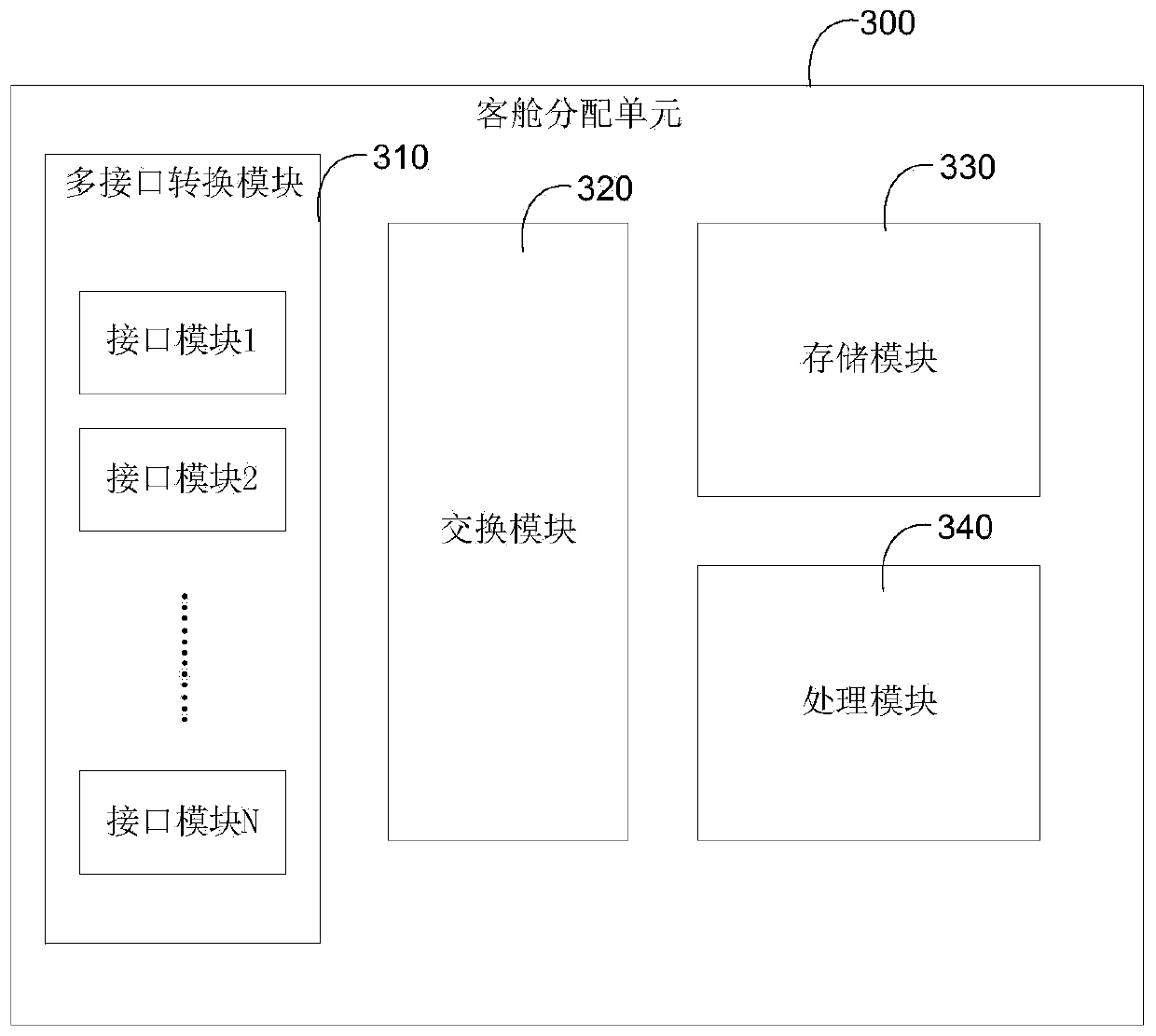
The invention discloses an aircraft cabin data distribution method and system. The aircraft cabin data distribution system may include a cabin control unit and a cabin distribution unit, the cabin distribution unit including: a first exchange module for exchanging data with the cabin control unit; a first interface module comprising a first interface for coupling to a first terminal device arranged in an aircraft cabin and transmitting data in a first format with the first terminal device; and a second interface module including a second interface for coupling to a second terminal device disposed within the aircraft cabin and transmitting data in a second format with the second terminal device, wherein the first interface and the second interface have different interface types. The invention further discloses an aircraft cabin data distribution method.

Description

technical field [0001] The invention relates to an aircraft system, in particular to an aircraft cabin data distribution method and system. Background technique [0002] There are various data in the aircraft cabin that need to be transmitted between the control system and the terminal equipment located in different positions in the aircraft cabin, such as audio data, cabin lighting control data, passenger service data, adjustable porthole data, etc. The characteristic of the above data transmission is that the terminal equipment is distributed throughout the aircraft cabin, and the types of data interfaces used by these terminal equipment are not uniform, such as Ethernet, CAN, RS485, analog audio, discrete hard wire, etc. [0003] The existing aircraft cabin data distribution system deploys multiple independent data distribution networks according to different data application scenarios and interface types. Each data distribution network includes a head-end controller and ...

Claims


Application Information

Patent Timeline
Patent Type & Authority Applications(China)
IPC IPC(8): H04L29/08G06F13/38G06F13/40G06F13/42
CPCG06F13/387G06F13/4068G06F13/4282G06F2213/0002H04L67/12
Inventor 陆曦邹照亮朱青李庆瑞朱旭张旭
Owner COMAC
Learn More