Multi-machine parallel power-taking power generation system

A technology of parallel connection and generator, which is applied in the direction of control device, auxiliary drive device, transportation and packaging, etc., which can solve the problems such as the inability to install high-power generators, achieve high social and economic benefits, and reduce production costs

Pending Publication Date: 2019-10-18
JIANGXI QINGHUA TAIHAO SANBO ELECTRICAL MACHINE
View PDF0 Cites 0 Cited by
  • Summary
  • Abstract
  • Description
  • Claims
  • Application Information

AI Technical Summary

Problems solved by technology

[0003] The purpose of the present invention is to provide a multi-machine parallel power generation system to solve the problem that a high-power generator cannot be installed in a small space, and at the same time greatly shorten the production cycle and improve social competitiveness

Method used


Image

  • Multi-machine parallel power-taking power generation system
  • Multi-machine parallel power-taking power generation system
  • Multi-machine parallel power-taking power generation system

Examples


Embodiment Construction

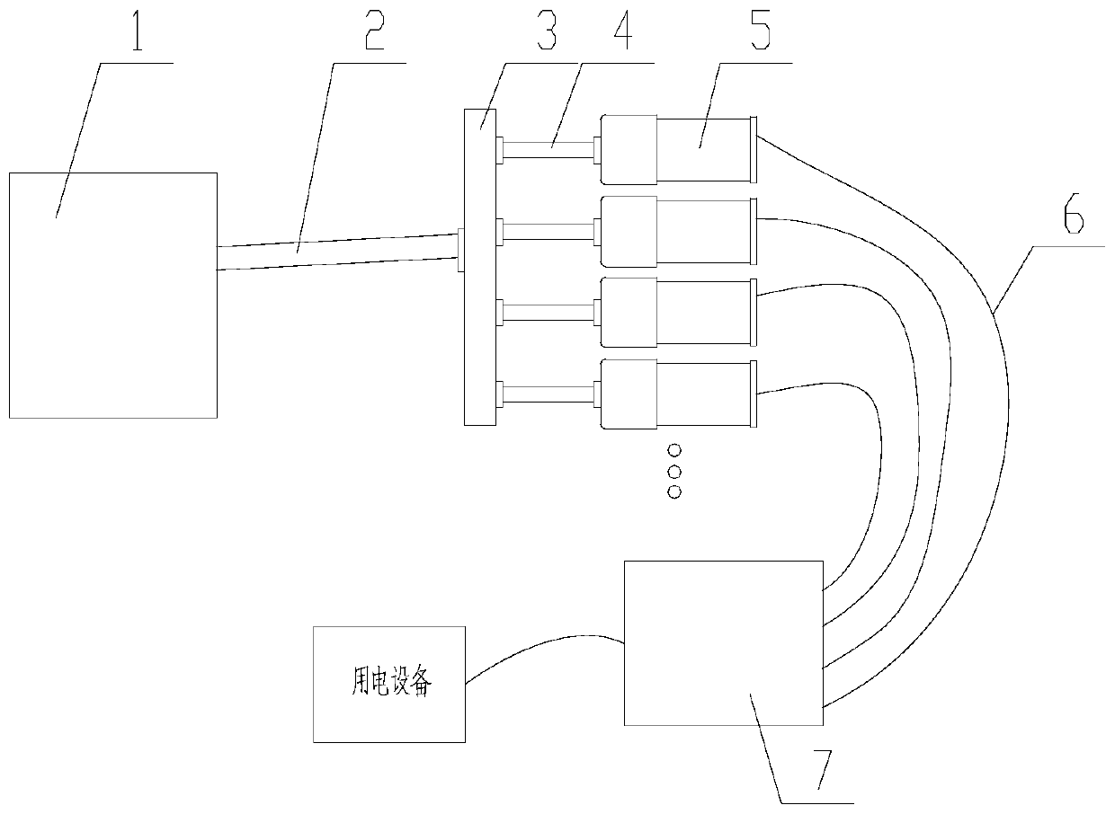
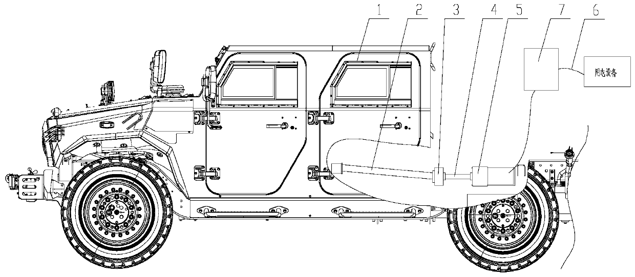
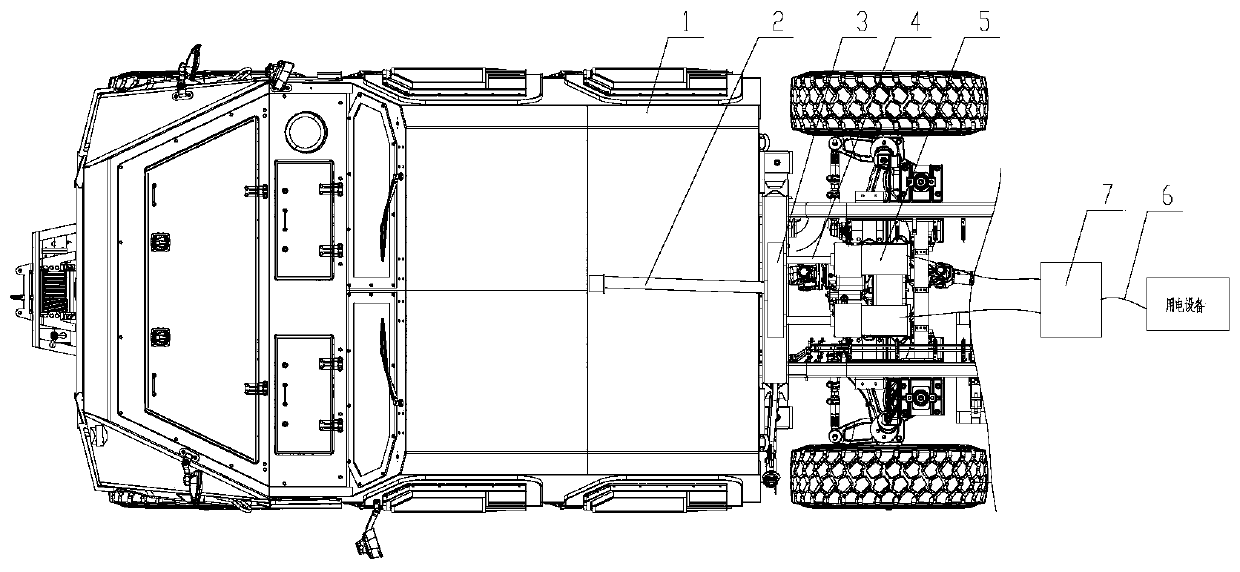
[0018] Such as figure 1 As shown, a multi-machine parallel power generation system of the present invention includes a main transmission shaft 2 , a gearbox 3 , several sub-transmission shafts 4 , several generators 5 , several connecting cables 6 and an inverter 7 . Automobile chassis (with power take-off) 1 provides the power source of the system, one end of the main drive shaft 2 is connected to the power take-off, the other end of the main drive shaft 2 is connected to the gearbox, and the power is transmitted to the gearbox 3 through the main drive shaft 2. Gear box 3 splits the output after shifting; the gear box 3 is a one-way input multiple output gear box, the gear box 3 is connected with one end of several sub-transmission shafts 4 respectively, and the other end of several sub-transmission shafts 4 is respectively connected with several generators 5 connected, the power is transmitted to each generator 5 through the transmission shaft 4; several generators 5 are con...


PUM


Abstract

The invention provides a multi-machine parallel power-taking power generation system. The system is used on an automobile with a power takeoff. The system involves a main transmission shaft connectedwith the power takeoff, a plurality of branch transmission shafts, a plurality of generators and inverters, wherein the main transmission shafts are connected with the branch transmission shafts through gear boxes; the generators are connected with the branch transmission shafts respectively; the inverters are electrically connected with the generators respectively. According to the multi-machineparallel power-taking power generation system, a traditional mode that a single high-power generator is used for generating electricity is abandoned, a mode of paralleling a plurality of small-power generator to supply power is adopted, the problem of large-power generation in a narrow space of a chassis is solved, the system is suitable for fighting power supply requirements in advancing of modern weapon equipment, and the system has relatively high social benefits and economic benefits.

Description

technical field [0001] The invention relates to a power generation system, in particular to a multi-machine parallel connection power generation system. Background technique [0002] At present, the power generation system is generally divided into two types, one is the power generation system where the generator is installed at the engine of the automobile chassis; the other is the power generation system where the generator is installed at the power outlet of the automobile chassis. In the first case, the generator needs to be specially designed and developed according to the condition of the automobile chassis, and it must be fully considered in the early design stage of the chassis, which greatly increases the development cycle of the automobile chassis. At the same time, once the generator is installed, it cannot be effectively maintained, and the maximum power is constant, resulting in waste of low-power electrical equipment and insufficient high-power electrical equip...

Claims


Application Information

Patent Timeline
Patent Type & Authority Applications(China)
IPC IPC(8): B60K25/06
CPCB60K25/06
Inventor 路尔旺王智群马逢行
Owner JIANGXI QINGHUA TAIHAO SANBO ELECTRICAL MACHINE
Why Eureka
Try Eureka