Suction table with workpiece support for workpiece to be supported

A workpiece and support technology, applied in the field of suction table, can solve the problem of not being able to move freely

Active Publication Date: 2022-07-05
ESTA APPBAU
View PDF10 Cites 0 Cited by
  • Summary
  • Abstract
  • Description
  • Claims
  • Application Information

AI Technical Summary

Problems solved by technology

[0003] These processing tables are often fixed in the workshop and therefore cannot be moved freely

Method used


Image

  • Suction table with workpiece support for workpiece to be supported
  • Suction table with workpiece support for workpiece to be supported
  • Suction table with workpiece support for workpiece to be supported

Examples


Embodiment Construction

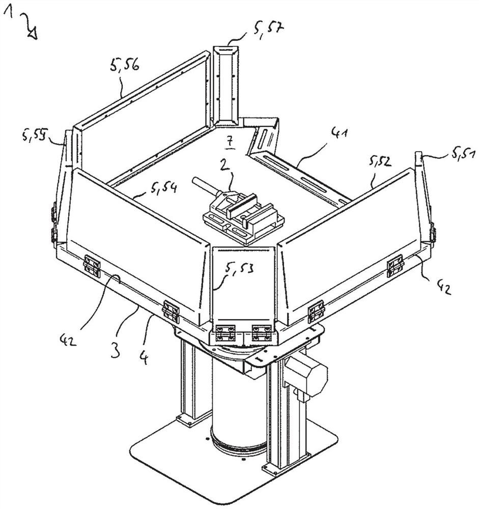
[0039] exist figure 1 An exemplary suction table 1 is shown with a workpiece support 2 for the workpiece to be supported.

[0040] The workpiece carrier 2 is designed to be fixed in position, below and to the side of the workpiece carrier 2 are arranged suction devices 3 , by means of which the particles and / or gases in the exhaust gas flow can be discharged downwards.

[0041] In this case, the suction device 3 is arranged relative to the workpiece carrier 2 around this workpiece carrier and is designed to be rotatable about the workpiece carrier 2 .

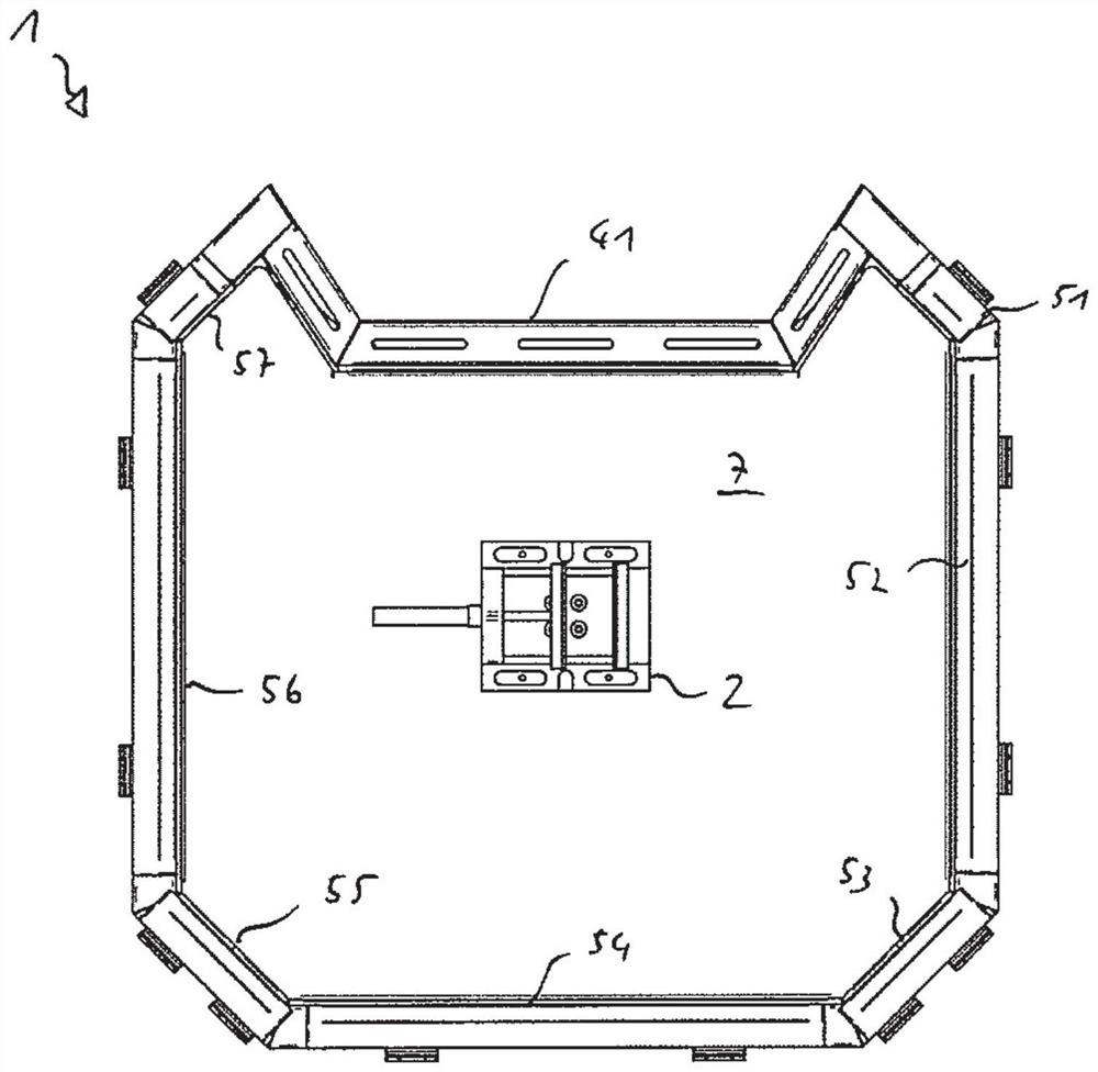
[0042] The suction device 3 is designed in the form of a cap 4, see also figure 2 , and has a recess 41 on one side for the person P working on the suction table 1 .

[0043] The suction device 3 has a plurality of hinged side walls 5 , 51 to 57 on the upper edge 42 of the cap 4 .

[0044] The side walls are not hinged in the region of the recess 41 in order to enable free access for workers.

[0045] The suction device 3 ...


PUM


Abstract

The invention relates to a suction table (1) with a workpiece support (2) for the workpiece to be supported, wherein the workpiece support (2) is designed to be stationary, wherein in the A suction device (3) is arranged below and / or on the side of the workpiece support (2), by means of which the particles and / or gases in the exhaust gas flow can be discharged downwards, wherein the suction device (3) It is arranged around this workpiece support ( 2 ) relative to the workpiece support and is designed to be rotatable about the workpiece support ( 2 ).

Description

technical field [0001] The invention relates to a suction table with a workpiece support for the workpiece to be supported. Background technique [0002] Workpiece supports are usually mounted on the machining table. If the processing table is designed as a suction table, it is sucked downwards, backwards or sideways. [0003] These machining tables are often fixed in the workshop and therefore cannot move freely. Workers clamp their machined parts into stationary, stationary and movement-resistant tool holders and have to move tools or machines (eg angle grinders) that are in some ergonomically disadvantageous positions during machining. In addition, the workpiece sometimes has to be circled several times in order to reach all machining sides. [0004] As an alternative to suction tables, suction hoods can be used, which must likewise follow - in order to be able to collect falling dust - two-handed operation here constitutes a problem. SUMMARY OF THE INVENTION [000...

Claims


Application Information

Patent Timeline
Patent Type & Authority Patents(China)
IPC IPC(8): B08B15/00B08B15/02B23Q1/00B25H1/20B25H1/14B25H1/16
CPCB08B15/02B25H1/16B25H1/20B25H1/02B23Q1/25B23Q1/522B23Q11/0046B23Q11/0891B23Q2220/004B08B1/00B23Q2703/02
Inventor 塞巴斯蒂安·克拉特丹尼尔·帕尔梅罗-罗勒德
Owner ESTA APPBAU
Why Eureka
Try Eureka