
Clamping mechanism with positioning structure

A technology of clamping mechanism and positioning structure, which is applied in the direction of chucks, manipulators, manufacturing tools, etc., can solve problems such as difficulty in ensuring clamping accuracy and stability, limitations in applicability and practicability, and affect processing efficiency, etc., to achieve practicality Good, strong applicability, and efficiency-enhancing effects

Inactive Publication Date: 2019-10-08
刘逸
View PDF0 Cites 3 Cited by
  • Summary
  • Abstract
  • Description
  • Claims
  • Application Information

AI Technical Summary

Problems solved by technology

[0002] In the process of hardware processing, various processing and assembly are generally required, and clamping operations are generally required in the process of processing and assembly. However, in the traditional technology, manual clamping operations are mostly used, which is not only time-consuming and laborious, but also difficult to ensure clamping. The accuracy and stability of the machine will also seriously affect the efficiency of processing, so the applicability and practicability are limited

Method used


Image

  • Clamping mechanism with positioning structure
  • Clamping mechanism with positioning structure

Examples


Embodiment 1)

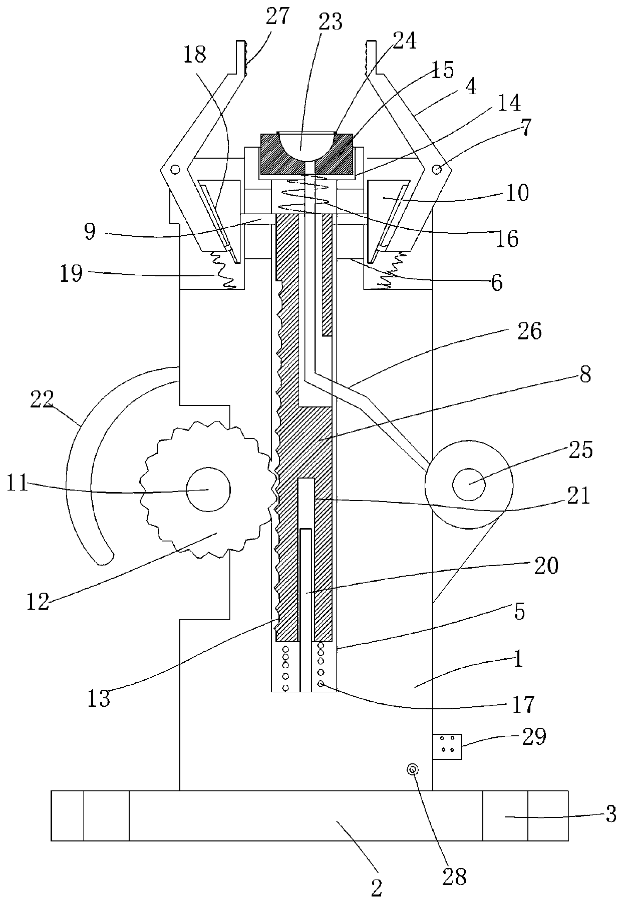
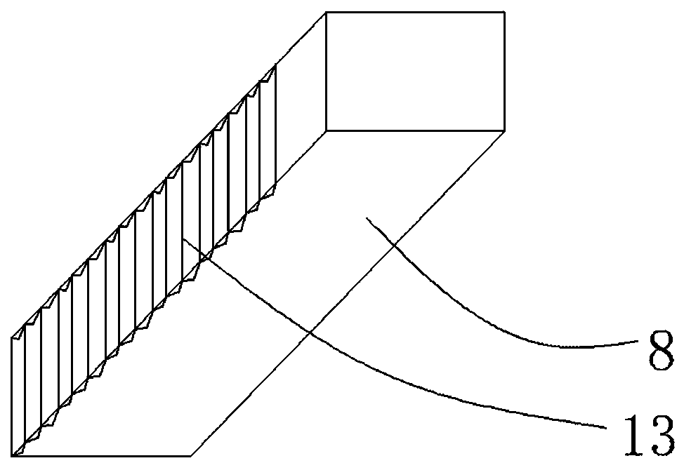
[0017] figure 1 and figure 2 A specific embodiment of the invention is shown in which figure 1 It is a structural schematic diagram of the present invention; figure 2 It is a concrete structural diagram of the structure of the square pole in the present invention.

[0018] See figure 1 and figure 2 , a clamping mechanism with a positioning structure, including a base 1, a mounting panel 2 is integrally formed at the bottom of the base, and a mounting screw hole 3 is fixed on the mounting panel, and the base is fixed on the mounting panel through the mounting panel On the corresponding processing machine, a clamping plate 4 is provided on the top of the base, a square vertical hole 5 with an open top surface is provided in the base, and a vertical vertical hole 5 is provided on the symmetrical side wall upper part of the base. To the chute 6, the clamping pressure plate is an L-shaped pressure plate and the corner of the clamping pressure plate is connected to the base ...


PUM


Abstract

The invention discloses a clamping mechanism with a positioning structure. The clamping mechanism comprises a base, a mounting panel is integrally formed on the bottom of the base, a clamping pressingplate is arranged on the top of the base, a square vertical hole with an opening in the top face is formed in the base, vertical sliding grooves are formed in the upper parts of the symmetrical sidewalls of the base, the clamping pressing plate is an L-shaped pressing plate, corners of the clamping pressing plate are connected to the base through movable shafts, a square column rod is arranged in the square vertical hole, supporting rib rods are arranged in the vertical sliding grooves, and right-angled triangular abutting blocks are fixed to the outer side ends of the supporting rib rods; and the inner side face of a bottom rod of the L-shaped pressing plate is attached to the inclined edge of each right-angled triangular abutting block, a drive motor is fixed to the side portion of thebase, and a drive gear is fixed to a main shaft of the drive motor. The clamping mechanism is reasonable in structure arrangement, clamping operation is realized effectively and quickly, the clampingstability is ensured, the labor intensity of a worker is reduced, the clamping efficiency is improved, the applicability is strong, and the practicability is good.

Description

technical field [0001] The invention belongs to the technical field of machining equipment, and in particular relates to a clamping mechanism with a positioning structure. Background technique [0002] In the process of hardware processing, various processing and assembly are generally required, and clamping operations are generally required in the process of processing and assembly. However, in the traditional technology, manual clamping operations are mostly used, which is not only time-consuming and laborious, but also difficult to ensure clamping. At the same time, it will seriously affect the efficiency of processing, so the applicability and practicability are limited. Contents of the invention [0003] The purpose of the present invention is to provide a clamping mechanism with a positioning structure with reasonable structure and strong applicability. [0004] The technical solution to achieve the purpose of the present invention is a clamping mechanism with a pos...

Claims


Application Information

Patent Timeline
Patent Type & Authority Applications(China)
IPC IPC(8): B25J15/02B25J15/08B25J15/00
CPCB25J15/00B25J15/0206B25J15/08
Inventor 刘逸
Owner 刘逸
Learn More