Multiply cable convenient pay-off unit

A pay-off device and convenient technology, which can be used in transportation and packaging, transportation of filamentous materials, thin material processing, etc., can solve the problems of time-consuming, labor-intensive, low-efficiency, and labor-intensive

Active Publication Date: 2019-09-27
ZIGONG POWER SUPPLY COMPANY STATE GRID SICHUAN ELECTRIC POWER
View PDF9 Cites 2 Cited by
  • Summary
  • Abstract
  • Description
  • Claims
  • Application Information

AI Technical Summary

Problems solved by technology

Traditionally, after winding the cable with a single pay-off reel, the cable is manually pulled to pay off the cable, but the traditional cable pay-off reel or pay-off device can only be used to release one cable alone. When there are many cables to be laid and multiple cables need to be laid at the same time, the efficiency of using traditional pay-off wheels or pay-off devices is very low, time-consuming and labor-intensive.
Now there is also a method of setting multiple pay-off wheels side by side to pay out multiple cables at the same time, but it is still necessary to manually pull the cables for pay-off during the pay-off process, and the work intensity of the staff is relatively high. prone to intertwining
Moreover, the diameter of the traditional pay-off wheel cannot be adjusted according to the actual length of the cable that needs to be paid off. When the cable pay-off length is long and the diameter of the pay-off wheel is small, many layers of cables will be wound on the pay-off wheel. , It will also cause the problem of winding between the cables; when the length of the cable pay-off is short and the distance between the pay-off reels is large, the pay-off reel did not completely wind the cable in the last century, and the excessively large pay-off reel It will take up too much space and is not convenient for the staff to operate
Therefore, for the traditional pay-off wheel or pay-off device, multiple cables cannot be paid out synchronously, multiple cables are easily entangled with each other when paying off, manually pulling the cables to pay off is labor-intensive, and the diameter of the pay-off wheel cannot be adjusted. To solve the problem of not matching the actual pay-off length, the invention discloses a convenient multi-cable pay-off device

Method used


Image

  • Multiply cable convenient pay-off unit
  • Multiply cable convenient pay-off unit
  • Multiply cable convenient pay-off unit

Examples


Embodiment 1

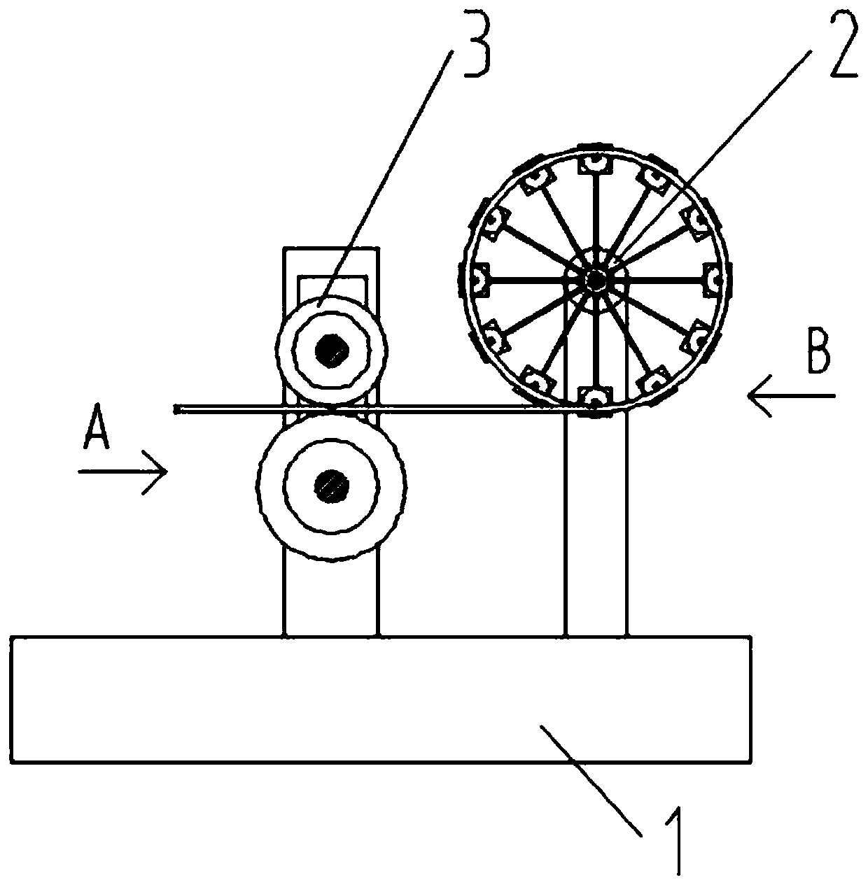
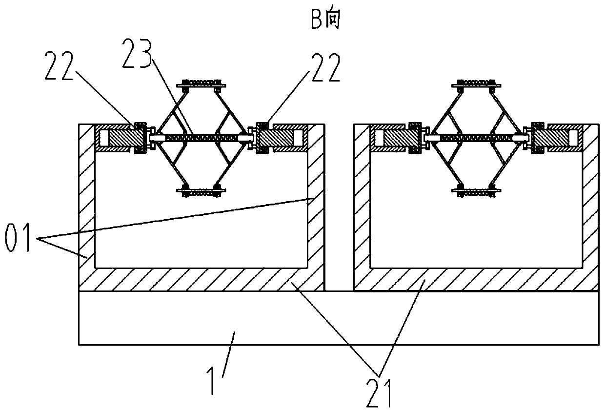
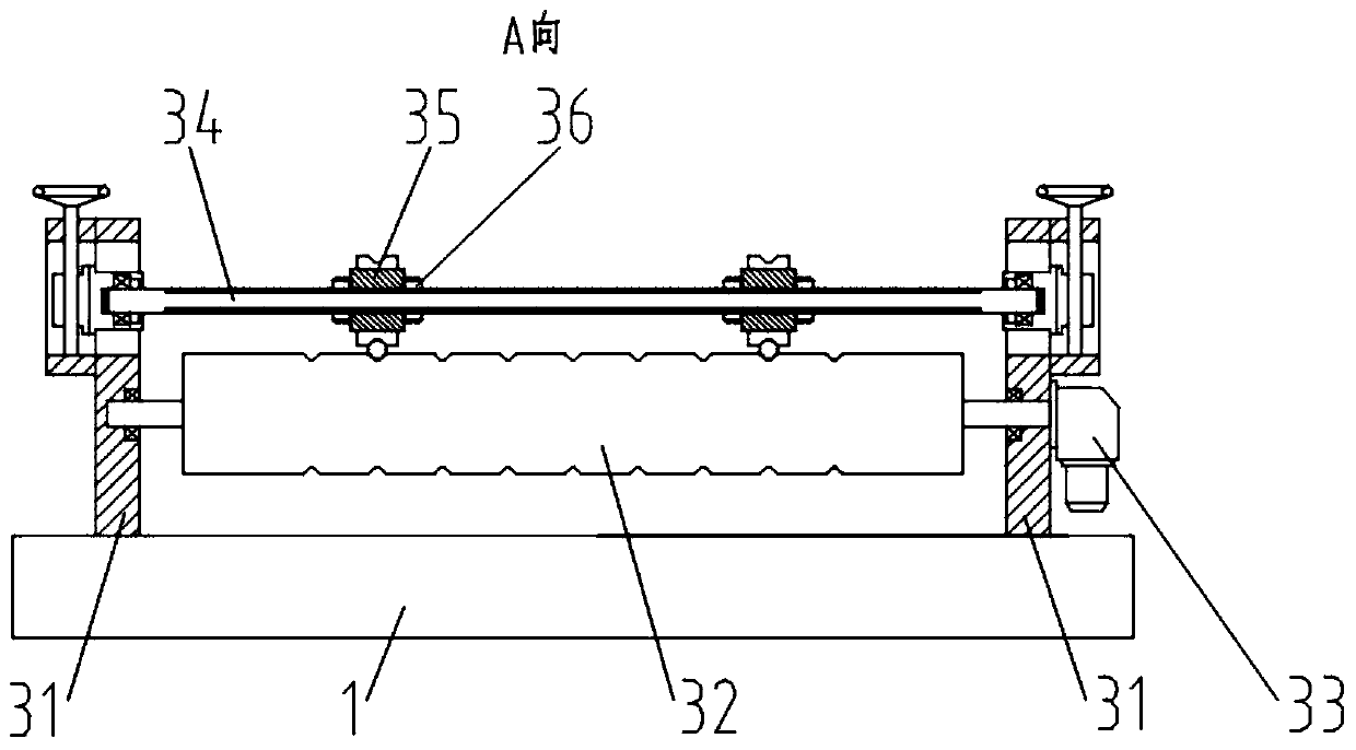
[0039] A convenient multi-cable pay-off device in this embodiment, such as Figure 1-Figure 3 As shown, it includes a base 1, which is characterized in that the base 1 is sequentially provided with a wire-feeding assembly 2 and a wire-feeding assembly 3 along the wire-releasing direction, and the wire-releasing assembly 2 is installed on the base 1 in sequence perpendicular to the wire-releasing direction. Several pay-off racks 21 on the top, the pay-off rack 21 includes two vertical columns 01 arranged symmetrically perpendicular to the wire-drawing direction, and the side near the top of the adjacent column 01 is respectively provided with a pay-off wheel seat 22, adjacent The variable diameter pay-off wheel 23 is rotated and installed between the pay-off wheel seats 22; the wire feed assembly 3 includes support frames 31 symmetrically arranged on both sides of the top of the base 1 along the line-release direction, and adjacent support frames 31 A power roller 32 is arrange...

Embodiment 2

[0046] This embodiment is further optimized on the basis of embodiment 1, such as Figure 4 As shown, the variable-diameter pay-off wheel 23 includes a variable-diameter axle 231, a movable sleeve 232, a fixed sleeve 233, a pole 234, a strut 235, a mounting plate 236, a rotating pin 237, and a locking member 238. A variable-diameter axle 231 is rotatably installed between the wheel bases 22, and a fixed sleeve 233 is fixed on both sides of the variable-diameter axle 231 symmetrically. The two sides of the fixed sleeve 233 are respectively hinged with one end of the strut 235 through the first hinge part, and the other end of the strut 235 is fixedly provided with a mounting plate 236; A movable sleeve 232 is arranged on the symmetrical sliding sleeve on the axial section between them. On the outer surface of the movable sleeve 232, a number of second hinge parts are arranged on the outer surface of the movable sleeve 232 along the circumferential direction corresponding to the...

Embodiment 3

[0053] This embodiment is further optimized on the basis of above-mentioned embodiment 1 or 2, such as Figure 5 As shown, a cross-column 02 is arranged between the tops of the adjacent columns 01 perpendicular to the direction of setting out the line, and the end of the cross-column 02 away from the column 01 is coaxially provided with a threaded mounting hole, and the threaded mounting hole is screwed. There is a connecting post 03 , the connecting end of which is protruding from the outside of the threaded mounting hole and is rotatably connected to one side of the pay-off reel seat 22 .

[0054] By rotating the connecting column 03, the depth of the connecting column 03 inserted into the threaded mounting hole on the horizontal column 02 can be adjusted. The column 03 is inserted into the threaded mounting hole synchronously, and the distance between the connecting columns 03 on both sides increases at this time, that is, the distance between the pay-off reel seats 22 on b...


PUM


Abstract

The invention discloses a multiply cable convenient pay-off unit. The multiply cable convenient pay-off unit comprises a pay-off component and a wire feeding component on a base, wherein the pay-off component comprises pay-off racks sequentially mounted on the base in a direction vertical to the pay-off direction, each pay-off rack comprises two stand columns symmetrically arranged in a direction vertical to the pay-off direction, pay-off wheel seats are respectively arranged at tops, close to each other, of the adjacent stand columns, and a reducing wire wheel is mounted between adjacent pay-off wheel seats; the wire feeding component comprises supporting frames symmetrically arranged on the two sides of the top of the base in the pay-off direction, and a power idler wheel is rotationally arranged between the bottoms of adjacent supporting frames; a forcing spindle is arranged in the vertical direction between the tops of the adjacent supporting frames in a sliding manner, and a compressing wheel is arranged on the forcing spindle in a sliding manner; the multiply cable convenient pay-off unit provided by the invention has the beneficial effects that the collecting and the transporting of multiply sets of cables can be performed synchronously, pay-off wheels with direction widths can be mounted compatibly, the mounting of the pay-off wheels is quick and convenient, the pay-off diameter can be adjusted, cables with different diameters and in different coming directions can be clamped and transported compatibly, and multiply cables are prevented from mutual intertwining.

Description

technical field [0001] The invention belongs to the technical field of wire-releasing in the electric power industry, and in particular relates to a convenient wire-releasing device for multiple cables. Background technique [0002] When laying cables in the power industry, safe and orderly pay-off is the prerequisite for normal cable laying operations. Traditionally, after winding the cable with a single pay-off reel, the cable is manually pulled to pay off the cable, but the traditional cable pay-off reel or pay-off device can only be used to release one cable alone. When there are many cables to be laid and multiple cables need to be laid at the same time, the efficiency of using traditional pay-off reels or pay-off devices is very low, time-consuming and labor-intensive. Now there is also a method of setting multiple pay-off wheels side by side to pay out multiple cables at the same time, but it is still necessary to manually pull the cables for pay-off during the pay-o...

Claims


Application Information

Patent Timeline
Patent Type & Authority Applications(China)
IPC IPC(8): B65H49/18B65H49/32B65H75/24B65H49/36B65H57/14B65H57/16
CPCB65H49/18B65H49/324B65H49/36B65H57/14B65H57/16B65H75/242
Inventor 王晓毅郑航吴玲朱晓贤
Owner ZIGONG POWER SUPPLY COMPANY STATE GRID SICHUAN ELECTRIC POWER
Why Eureka
Try Eureka