Photovoltaic tracking bracket and eccentric compensation device
A technology of compensation device and support device, applied in the direction of control using feedback, can solve problems such as manufacturing and installation of tracking brackets
- Summary
- Abstract
- Description
- Claims
- Application Information
AI Technical Summary
Problems solved by technology
Method used
Image
Examples
no. 1 example
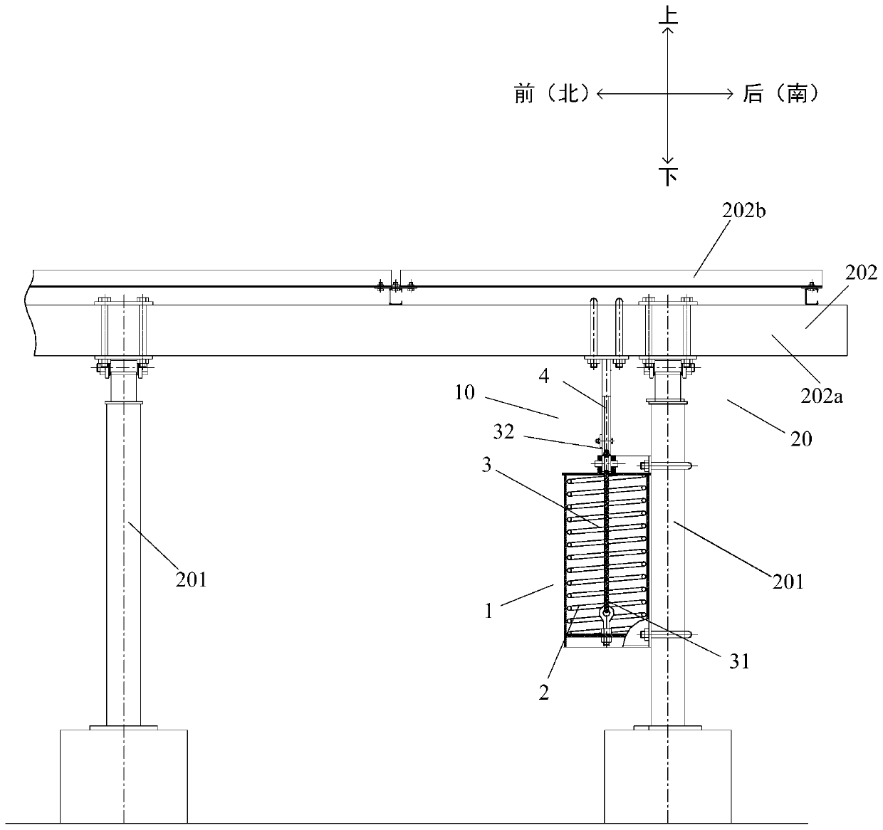
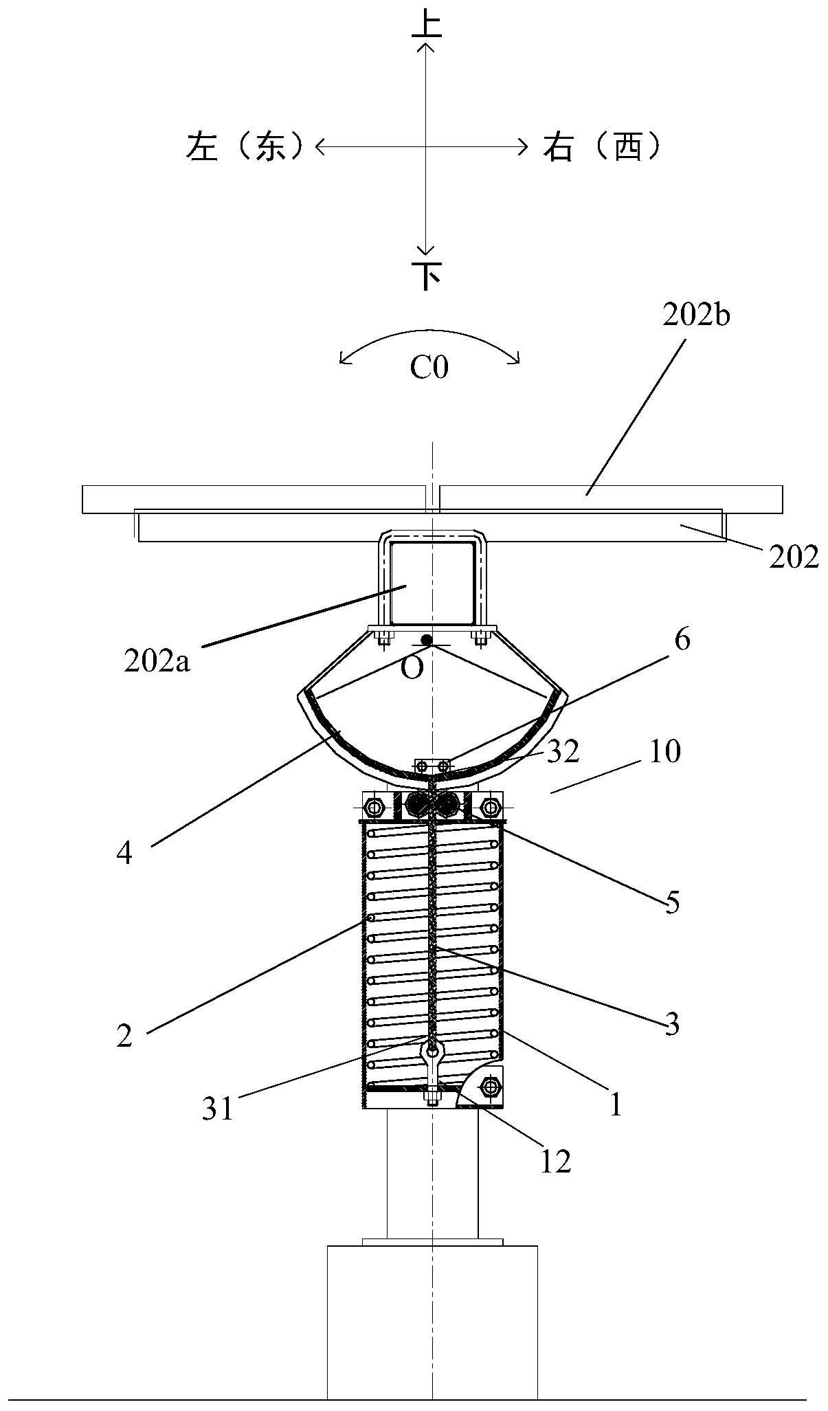
[0037] figure 1 and figure 2 It shows that the eccentricity compensation device 10 is applied to a photovoltaic tracking bracket 20 . The function or orientation of the eccentricity compensation device 10 is described below by taking the photovoltaic tracking bracket 20 as an example, but it does not limit the application environment of the eccentricity compensation device 10. The eccentricity compensation device 10 can also be applied to other similar scenarios that require eccentricity compensation. in scenarios involving rotating bodies.
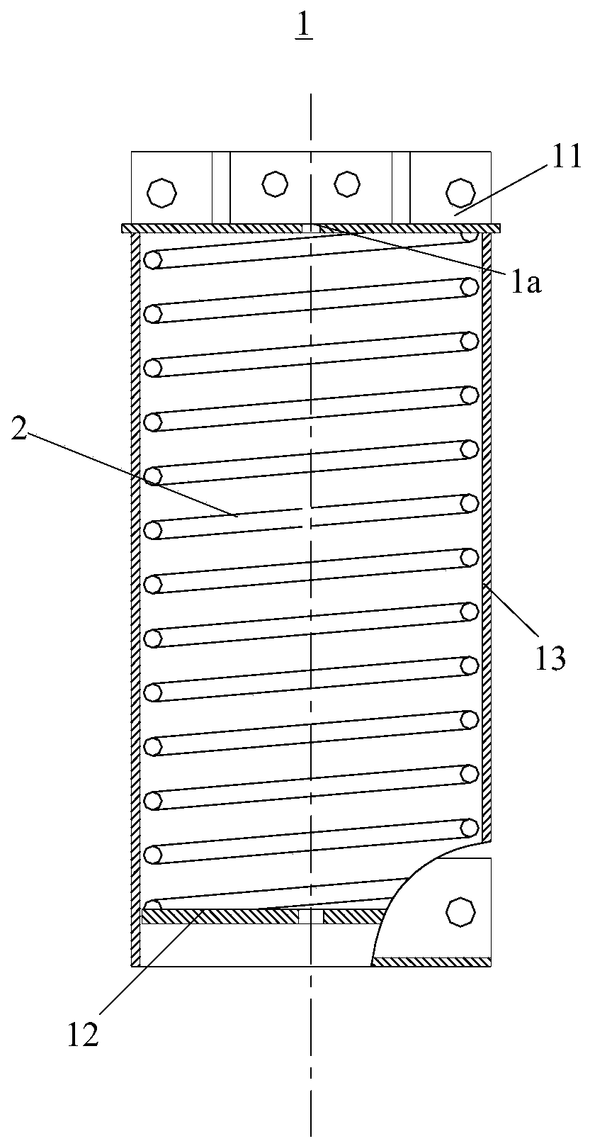
[0038] The photovoltaic tracking bracket 20 includes a rotating body 202 and a column 201 , and the rotating body 202 is rotatably supported by the column 201 . The rotating body 202 may include, for example, a main beam 202a extending along a north-south direction (or a front-rear direction) and a photovoltaic module 202b supported by the main beam 202a. The main beam 202a is rotatably supported by two uprights 201 arranged separatel...
no. 2 example
[0048] see below Figure 6 to Figure 8B The second embodiment is described, and the second embodiment uses the component numbers and partial content of the first embodiment, wherein the same numbers are used to denote the same or similar components, and the description of the same technical content is selectively omitted. For the description of the omitted part, reference may be made to the first embodiment, and the second embodiment will not be repeated.
[0049] In the first embodiment, the connecting member 4 is a sector wheel, while in the second embodiment, in the eccentric compensation device 10', the connecting member is a straight rod 4'. see Image 6 and Figure 7 , The end 400 of the straight rod 4' has a rope hole 402, and the end 32 of the flexible member 3 is fixed on the straight rod 4' through the rope hole 402.
[0050] For example, if Figure 8A and 8B As shown, the straight bar 4' is generally C-shaped, including two opposite vertical plates 401 and a ho...
PUM
 Abstract
Description
Claims
Application Information
 - Generate Ideas
- Intellectual Property
- Life Sciences
- Materials
- Tech Scout
- Unparalleled Data Quality
- Higher Quality Content
- 60% Fewer Hallucinations
Browse by: Latest US Patents, China's latest patents, Technical Efficacy Thesaurus, Application Domain, Technology Topic, Popular Technical Reports.
© 2025 PatSnap. All rights reserved.Legal|Privacy policy|Modern Slavery Act Transparency Statement|Sitemap|About US| Contact US: help@patsnap.com


