A charging pile that can be remotely controlled and automatically aligned with the charging head interface
What is Al technical title?
Al technical title is built by PatSnap Al team. It summarizes the technical point description of the patent document.
A technology of automatic alignment and charging head, applied in electric vehicle charging technology, charging stations, electric vehicles, etc., can solve problems such as charging and affecting charging operation
Active Publication Date: 2020-10-30
SHANDONG LANDBRIDGE PETROCHEMICAL CO LTD
View PDF8 Cites 0 Cited by
Summary
Abstract
Description
Claims
Application Information
AI Technical Summary
This helps you quickly interpret patents by identifying the three key elements:
Problems solved by technology
Method used
Benefits of technology
Problems solved by technology
[0002] The charging heads of traditional charging piles need to be aligned, and it is difficult to align them for charging in bad weather conditions, which greatly affects the charging operation
Method used
Image
Click on the blue label to locate the original text in one second.
Reading with bidirectional positioning of images and text.
Examples
Embodiment Construction
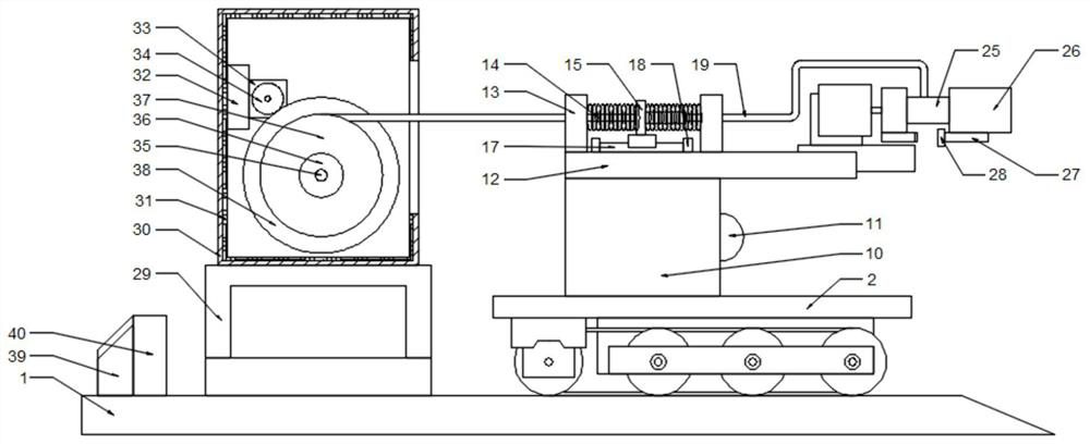
[0029] The present invention is specifically described below in conjunction with accompanying drawing, as Figure 1-5 As shown, a charging pile that can be remotely controlled and automatically aligned with the interface of the charging head includes a base 1, the base 1 is located above the ground, a storage mechanism is provided above the base 1, and a walking mechanism is provided inside the storage mechanism. A charging and walking detection mechanism is arranged above the traveling mechanism, and a charging head rotating mechanism is arranged inside the charging and walking detecting mechanism. mechanism, the walking mechanism includes a walking chassis 2 above the base 1, two walking stepping motor mounting frames 3 installed on the walking chassis 2, a walking stepping motor 4 installed on the walking stepping motor mounting frame 3, The walking power wheel 5 that is set on the walking stepper motor 4 rotating ends, two walking driven wheel supports 6 installed on the w...
PUM
Abstract
The invention discloses a charging pile capable of remote control and automatically aligning the interface of a charging head, including a base, characterized in that the base is located above the ground, and a storage mechanism is provided above the base, and a walking pole is provided inside the storage mechanism. Mechanism, above the walking mechanism, there is a charging and walking detection mechanism, inside the charging and walking detection mechanism, there is a charging head rotating mechanism, and one end of the charging head rotating mechanism is equipped with a charging adapter mechanism, and the receiving mechanism includes a wire take-up mechanism , a protection mechanism, a controller and a battery box are arranged above the base, the power input end of the controller is electrically connected to the battery box, and the power output end of the controller is respectively connected to the walking stepper motor, the monitoring camera, The line telescopic detection limit switch, the charging line, the charging joint rotating motor, the Hall sensor, and the line receiving motor are electrically connected, and the signal output terminals of the controller are respectively connected to the walking stepping motor, the charging line, the charging joint rotating motor, and the receiving line motor. The wire motor is electrically connected, and the signal input end of the controller is electrically connected with the monitoring camera, the wire stretch detection limit switch, and the Hall sensor respectively. The invention has the advantages of simple structure and strong practicability.
Description
technical field [0001] The invention relates to the field of charging piles, in particular to a charging pile that can be remotely controlled and automatically aligned with the interface of a charging head. Background technique [0002] The charging heads of traditional charging piles need to be aligned, and it is difficult to align them for charging in bad weather conditions, which greatly affects the charging operation. Contents of the invention [0003] The object of the present invention is to solve the above-mentioned problems by designing a charging pile that can be remotely controlled and automatically aligned with the interface of the charging head. [0004] To achieve the above object, the technical solution of the present invention is a charging pile that can be remotely controlled and automatically aligned with the interface of the charging head, including a base, the base is located above the ground, and a storage mechanism is provided above the base. There is...
Claims
Application Information
Patent Timeline
Application Date:The date an application was filed.
Publication Date:The date a patent or application was officially published.
First Publication Date:The earliest publication date of a patent with the same application number.
Issue Date:Publication date of the patent grant document.
PCT Entry Date:The Entry date of PCT National Phase.
Estimated Expiry Date:The statutory expiry date of a patent right according to the Patent Law, and it is the longest term of protection that the patent right can achieve without the termination of the patent right due to other reasons(Term extension factor has been taken into account ).
Invalid Date:Actual expiry date is based on effective date or publication date of legal transaction data of invalid patent.