Slider used for steam suspension test
It is a technology of sliding blocks for experiments, which is applied in the direction of laboratory appliances, laboratory clamping devices, supporting appliances, etc. It can solve the problems of large air resistance and excessive power, so as to reduce air resistance, increase the force bearing area, The effect of a good test environment
- Summary
- Abstract
- Description
- Claims
- Application Information
AI Technical Summary
Problems solved by technology
Method used
Image
Examples
Embodiment 1
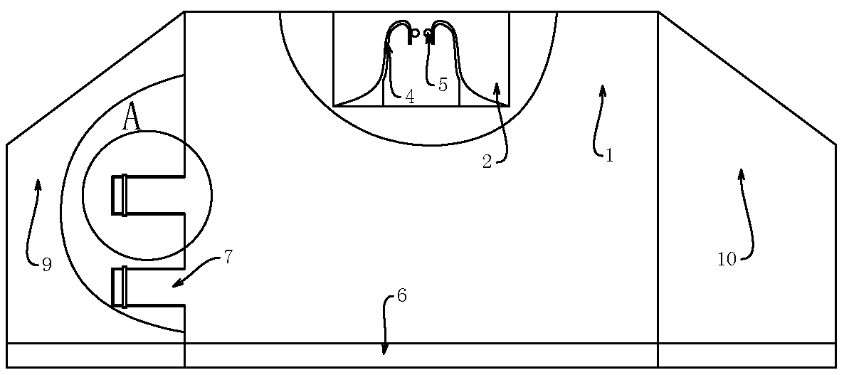
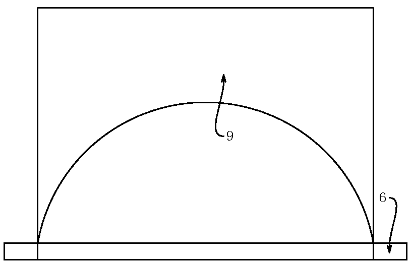
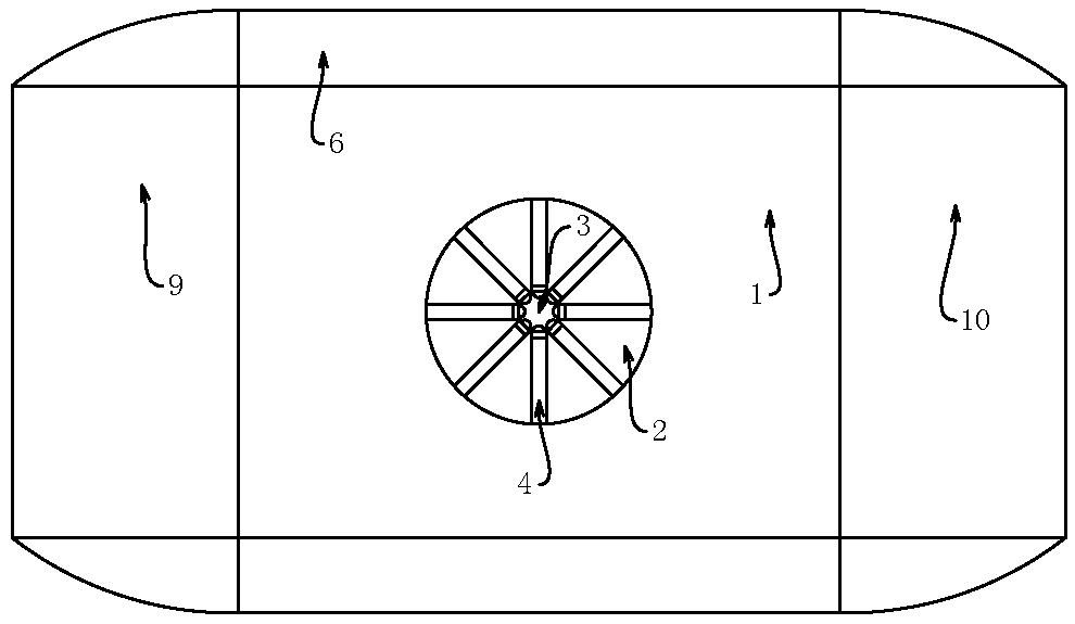
[0016] The slider for the steam suspension experiment includes a slider body 1. The slider body 1 is a rectangular block, and the bottom of the rectangular block is provided with a groove that is sunk into the inside of the rectangle block. The inside of the slider body 1 becomes a hollow structure, and the groove reduces the sliding. Due to the weight of the block body 1 itself, the groove is hemispherical, and the gas blows up the slider body 1 from the bottom. Due to the existence of the hemispherical groove, its contact area is more increased, so that the support slider does not need a large Gas power can achieve suspension. The upper center of the slider body 1 is provided with a cylindrical fixing hole 2 recessed into the slider body 1. The slider is used to complete various experiments. It is necessary to install various measurement physical quantities on the upper part of the slider body 1. For experimental equipment, the fixing hole 2 provides a place for it to be plac...
Embodiment 2
[0018] The four sides of the slider main body 1 near the bottom edge are provided with a rectangular plate 6 with the same length as the side. The lower surface of the rectangular plate 6 is flush with the lower surface of the slider main body 1. The area blown by the airflow bears more buoyancy from the airflow, reducing the airflow required by the airflow per unit area, thereby reducing energy consumption. The connection of the rectangular plate 6 at the bottom of the slider body 1 is connected by an arc, and four The arrangement of the rectangular plate 6 does not close the corners of the slider main body 1 , and the material of the rectangular plate 6 and the slider main body 1 is the same.
Embodiment 3
[0020] The front and rear ends of the slider main body 1 are provided with horizontal cylindrical connecting rods 7, the connecting rods 7 carry the connecting function, and the end of the connecting rods 7 away from the slider main body 1 is provided with a ring protrusion 8, the protrusion 8 is better The fixed connection block prevents it from slipping. The connecting rod 7 is respectively connected to the front connecting block 9 and the rear connecting block 10. The material of the front connecting block 9 and the rear connecting block 10 is the same as that of the slider main body 1, and the density of the same material is the same, so that the output of the air flow can be controlled more conveniently. The front connecting block 9 is the same as the rear connecting block 10. The cutting surface of the front connecting block 9 is a right-angled trapezoid, and the upper bottom surface of the right-angled trapezoid is provided with arc edges, which is more conducive to the ...
PUM
 Abstract
Description
Claims
Application Information
 - R&D
- Intellectual Property
- Life Sciences
- Materials
- Tech Scout
- Unparalleled Data Quality
- Higher Quality Content
- 60% Fewer Hallucinations
Browse by: Latest US Patents, China's latest patents, Technical Efficacy Thesaurus, Application Domain, Technology Topic, Popular Technical Reports.
© 2025 PatSnap. All rights reserved.Legal|Privacy policy|Modern Slavery Act Transparency Statement|Sitemap|About US| Contact US: help@patsnap.com


