Capacity control valve
A capacity control, control room technology, used in valve devices, valve details, liquid variable capacity machinery, etc.
- Summary
- Abstract
- Description
- Claims
- Application Information
AI Technical Summary
Problems solved by technology
Method used
Image
Examples
Embodiment 1
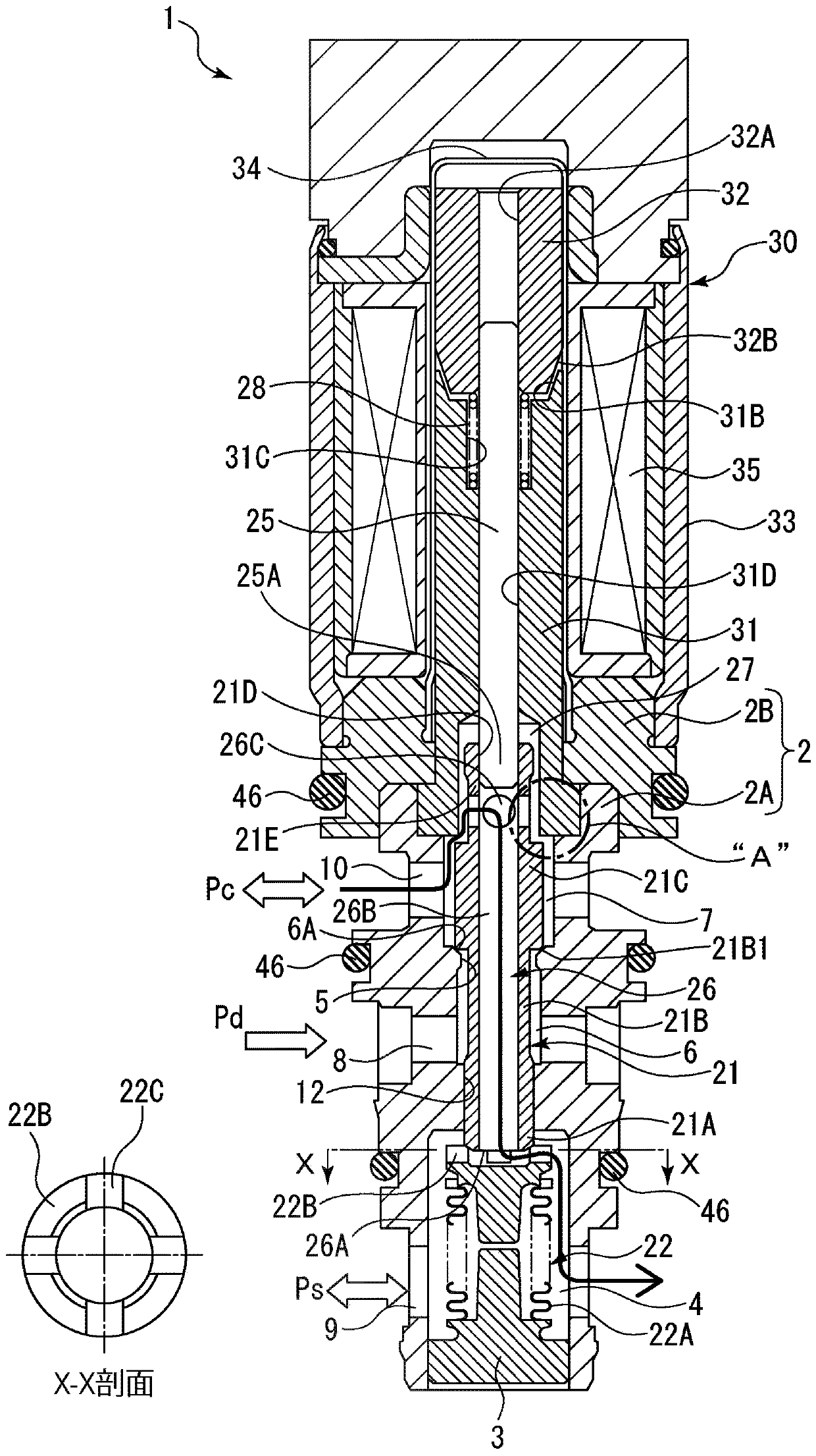
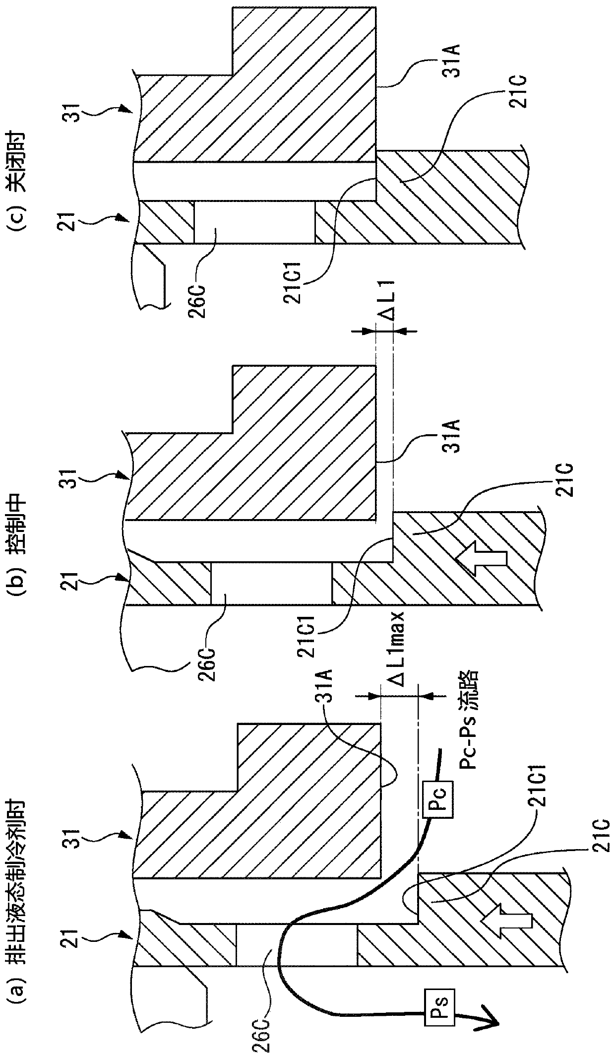
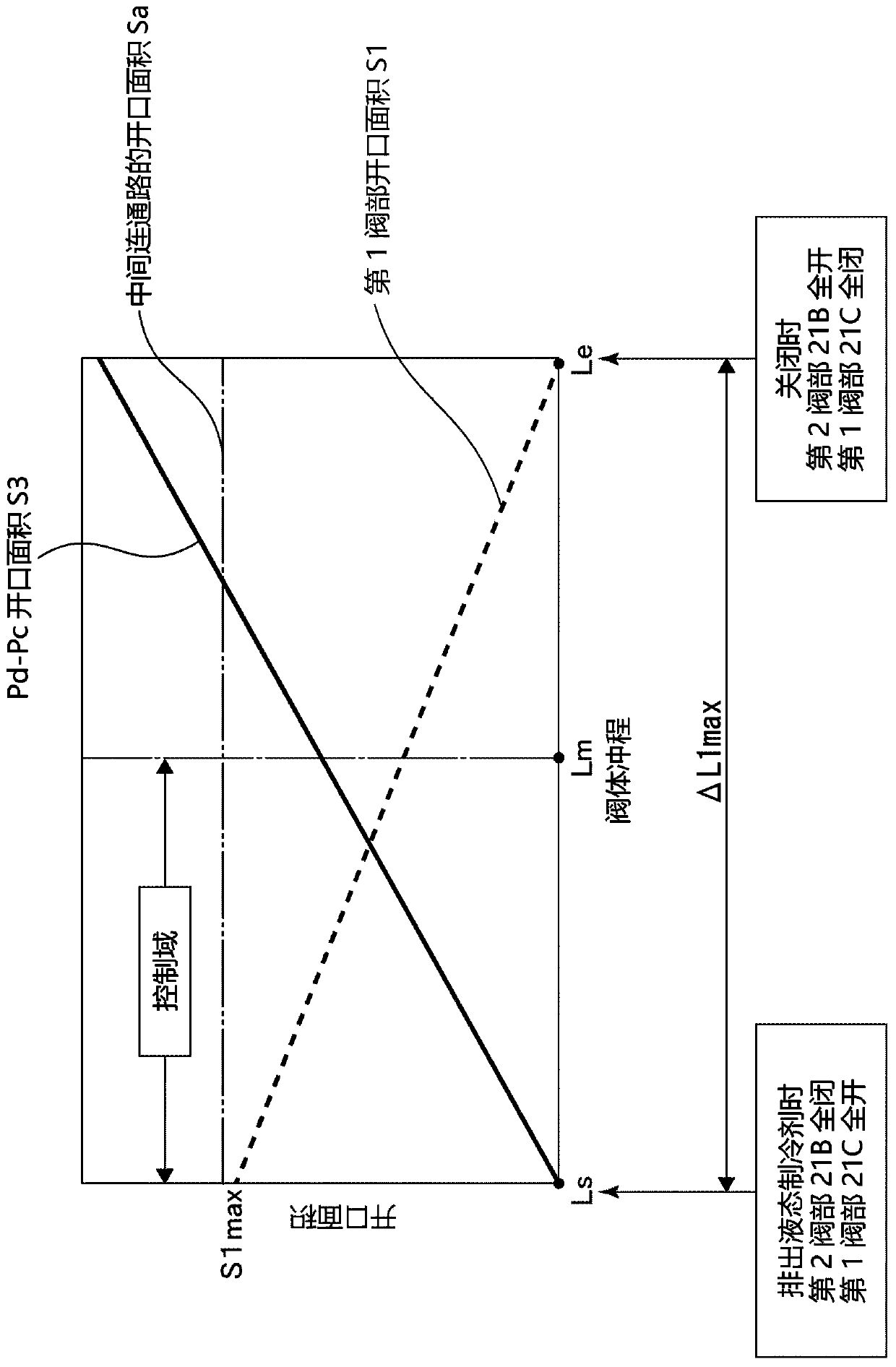
[0049] refer to Figure 1 to Figure 3 , the capacity control valve according to Embodiment 1 of the present invention will be described. exist figure 1 Among them, 1 is the capacity control valve. The capacity control valve 1 is mainly composed of a valve main body 2 , a valve body 21 , a pressure sensitive body 22 and a solenoid unit 30 . Hereinafter, the respective configurations constituting the capacity control valve 1 will be described.
[0050] The valve main body 2 is composed of a first valve main body 2A having a functioning through-hole therein, and a second valve main body 2B integrally fitted to one end portion of the first valve main body 2A. Furthermore, the first valve body 2A is made of metal such as brass, iron, aluminum, or stainless steel, or a synthetic resin material. On the other hand, since the second valve main body 2B functions as a magnetic circuit of the solenoid unit 30 , it is made of a magnetic material such as iron with low magnetic resistan...
Embodiment 2
[0079] refer to Figure 4 to Figure 6 A capacity control valve according to Embodiment 2 of the present invention will be described. The capacity control valve 50 according to the second embodiment is mainly different from the embodiment in that the first valve portion surface 21H formed at the boundary portion between the valve body first end portion 21E and the first valve portion 21G of the valve body 21 is formed of a tapered surface. Example 1 is different, but other basic configurations are the same as in Example 1, and the same symbols are assigned to the same components, and repeated descriptions are omitted.
[0080] Figure 4 It is a front sectional view showing the capacity control valve according to the second embodiment of the present invention. Figure 5 express Figure 4 The enlarged view of part B and the action state of the valve body 21.
[0081]The valve body 21 is a hollow cylindrical member, has an intermediate communication passage 26 inside the valve...
PUM
 Abstract
Description
Claims
Application Information
 - R&D
- Intellectual Property
- Life Sciences
- Materials
- Tech Scout
- Unparalleled Data Quality
- Higher Quality Content
- 60% Fewer Hallucinations
Browse by: Latest US Patents, China's latest patents, Technical Efficacy Thesaurus, Application Domain, Technology Topic, Popular Technical Reports.
© 2025 PatSnap. All rights reserved.Legal|Privacy policy|Modern Slavery Act Transparency Statement|Sitemap|About US| Contact US: help@patsnap.com


