
Unmanned aerial vehicle gravity center measurement and calibration device

A technology for a calibration device and an unmanned aerial vehicle, which is applied in the field of gravity center measurement of an unmanned aerial vehicle and the setting of a calibration device, can solve the problems of difficult operation, inconvenient use, inability to measure in real time, etc., and achieves convenient use, reliable results, and simple structure. Effect

Inactive Publication Date: 2019-09-13
高双柱
View PDF0 Cites 1 Cited by
  • Summary
  • Abstract
  • Description
  • Claims
  • Application Information

AI Technical Summary

Problems solved by technology

[0003] According to the traditional method of measuring the center of gravity of irregular objects, most of them use the vertical line method to measure the position of the center of gravity of the drone. Although this method is effective, it is difficult to implement because of the irregular surface of the fuselage. To calibrate the position of the center of gravity, two measurements are required
The most important thing is the hysteresis, that is, it can be measured after the equipment is installed, and it cannot be measured in real time, and then feedback to adjust the installation position of the electronic equipment, which is very inconvenient to use

Method used


Image

  • Unmanned aerial vehicle gravity center measurement and calibration device
  • Unmanned aerial vehicle gravity center measurement and calibration device
  • Unmanned aerial vehicle gravity center measurement and calibration device

Examples


Embodiment Construction

[0029] The present invention will be further described below in conjunction with specific embodiments, where the illustrative embodiments and illustrations are used to explain the present invention, but are not intended to limit the present invention.

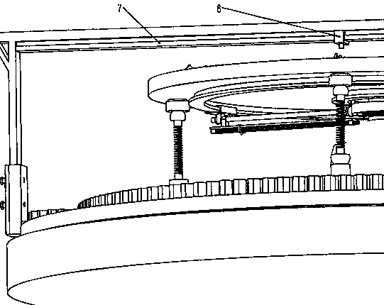
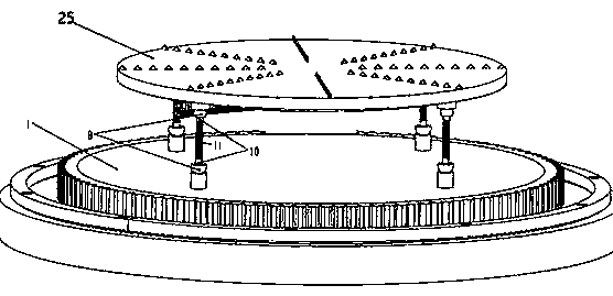
[0030] Because the four swing frames are equally divided on the inner circular track, and the other four four are equally divided on the outer circular track, and the swing frame on a certain inner circular track and a certain outer circular track are related to a certain The two spring seats are on the same radius line of the loading plate, so the Cartesian coordinate system is established with the radius line of the loading plate after the above-mentioned quartering, and the center point of the loading plate is the origin of the rectangular coordinate system.

[0031] When in use, the platform itself performs a quick self-balancing calibration: four small servo motors 22 act at the same time, and the four moving frames 21 are ...


PUM


Abstract

The invention provides an unmanned aerial vehicle gravity center measurement and calibration device, and belongs to the field of research of unmanned aerial vehicle accessory equipment. According to the design, automatic balance and automatic calibration are adopted, and the gravity center of the unmanned aerial vehicle can be rapidly measured and calibrated, so determination of an installation position of subsequent electronic equipment is facilitated; a polar coordinate scheme is adopted, double balance beams and an electromagnetic magnet are balanced, a process is rapid and agile, and the balance fluctuation is small; for a balanced vehicle body, a laser head or a calibration pen are adopted to calibrate the gravity center, and an observation effect is simple and clear; the device is convenient to use and can measure the gravity center of the unmanned aerial vehicle of any size.

Description

technical field [0001] The invention provides a center-of-gravity measurement and calibration device of an unmanned aerial vehicle, which belongs to the field of object gravity center measurement and calibration, in particular to the field of the center-of-gravity measurement and calibration device installation of an unmanned aerial vehicle. Background technique [0002] In the field of drone research, the measurement of the center of gravity has always been a difficult problem in the industry. Because of the installation of accessories such as subsequent electronic equipment, the center of gravity of the drone is often difficult to determine. During the installation process, constant debugging is required to ensure that the center of gravity appears where it needs to be, so as to meet the stability during flight. [0003] According to the traditional method of measuring the center of gravity of irregular objects, most of them use the vertical line method to measure the pos...

Claims


Application Information

Patent Timeline
Patent Type & Authority Applications(China)
IPC IPC(8): B64F5/60G01M1/12
CPCB64F5/60G01M1/12
Inventor 不公告发明人
Owner 高双柱
Learn More